Structure for anti-floating constraint of honeycomb core
A technology of honeycomb cores and columns, which is applied to building components, building structures, floors, etc., can solve the problems of affecting the quality of floors, inconvenient follow-up construction, and poor economy, so as to achieve small impact, increase the force-bearing area, and avoid damage Effect
- Summary
- Abstract
- Description
- Claims
- Application Information
AI Technical Summary
Problems solved by technology
Method used
Image

Examples
Embodiment 1
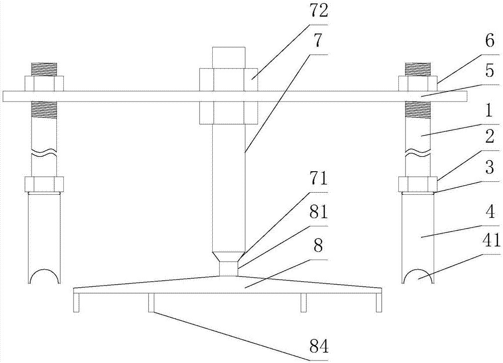
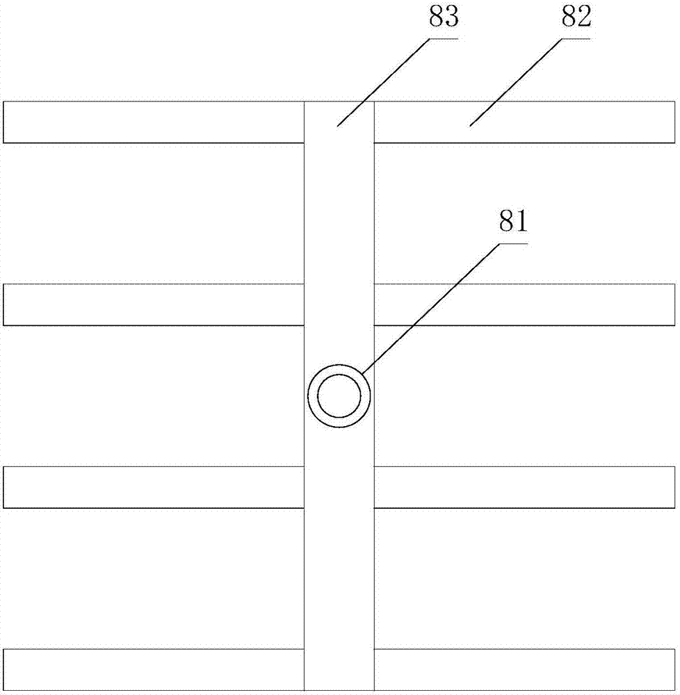
[0029] Such as figure 1 and figure 2 As shown, the structure used for the anti-floating constraint of the honeycomb core includes a frame body connected to the floor steel mesh, a pressure bar 7 connected to the frame body at the upper end, and a pressure plate 8 for placing on the upper surface of the honeycomb core;
[0030]Described frame body comprises vertical rod and crossbeam 5, and described vertical rod comprises connecting seat 4 and column 1, and described connecting seat 4 is provided with internally threaded hole, and the lower end of column 1 is threadedly connected with internally threaded hole, and described crossbeam 5 The upper end of the column 1 is pierced through the through hole provided thereon;
[0031] It also includes a second nut 6 screwed to the upper end of the column 1 , the lower end surface of the second nut 6 is in contact with the upper surface of the beam 5 .
[0032] In this scheme, the end face where the open end of the internal threaded...
Embodiment 2
[0036] Such as figure 1 and figure 2 As shown, this embodiment is further limited on the basis of Embodiment 1: in order to reduce the deformation of the crossbeam 5 when it is stressed, there are two vertical bars, and the two ends of the crossbeam 5 are provided with through holes. And the two through holes cooperate with the upper ends of the columns 1 on different vertical rods, and each column 1 is provided with a second nut 6 . In this solution, both ends of the crossbeam 5 are constrained, so that the axial direction of the pressure rod 7 and the column 1 is in the vertical direction as far as possible, so that the subsequent extraction of the pressure rod 7 and the column 1 and the reduction of the pressure rod can be facilitated. 7. The effect on the semi-cured concrete layer when the column 1 is pulled out.
[0037] During concrete pouring or concrete curing process, in order to prevent the slurry from entering the threaded connection surface of the column 1 and t...
Embodiment 3
[0045] This embodiment is further limited on the basis of any one of the technical solutions provided by any one of the above embodiments, such as figure 1 As shown, for the convenience of adjusting the position of the pressure bar 7 in the longitudinal direction of the crossbeam 5, the crossbeam 5 is also provided with a strip-shaped hole along its own length direction, and the strip-shaped hole runs through the upper and lower ends of the crossbeam 5, Two third nuts 72 are also threaded on the pressure rod 7, and the upper end of the pressure rod 7 is partially embedded in the strip-shaped hole, and the two third nuts 72 are respectively located on the upper and lower sides of the beam 5. side. In this scheme, when the position of the pressing plate 8 is fixed, if the length direction of the honeycomb core is parallel to the length direction of the steel bar used to connect the connecting seat 4 in the steel mesh, the connection position of the connecting seat 4 in the corre...
PUM
 Abstract
Description
Claims
Application Information
 - Generate Ideas
- Intellectual Property
- Life Sciences
- Materials
- Tech Scout
- Unparalleled Data Quality
- Higher Quality Content
- 60% Fewer Hallucinations
Browse by: Latest US Patents, China's latest patents, Technical Efficacy Thesaurus, Application Domain, Technology Topic, Popular Technical Reports.
© 2025 PatSnap. All rights reserved.Legal|Privacy policy|Modern Slavery Act Transparency Statement|Sitemap|About US| Contact US: help@patsnap.com