Infrared control power switch system

A technology for controlling power supply and switching system, applied in non-electrical signal transmission systems, signal transmission systems, electrical program control, etc. The effect of improving production cost and safety

Inactive Publication Date: 2017-11-07
HEFEI LIYUANJIE INFORMATION TECH CO LTD
View PDF2 Cites 0 Cited by
  • Summary
  • Abstract
  • Description
  • Claims
  • Application Information

AI Technical Summary

Problems solved by technology

[0003] At present, the indoor 220V power supply of the known technology all adopts a mechanical switch to control the power supply line. Sometimes people forget to turn off the power supply and leave the room during use, resulting in waste of electric energy. Especially in enterprises, institutions and hotels, when the air conditioner is working, people who can smoke Often the door or window is opened, which causes increased power consumption and wastes energy. Moreover, the known power switches do not have real-time monitoring functions. They cannot be automatically cut off when the power switch is overvoltage or overcurrent, nor can it be remotely controlled. Control the opening or closing of the power switch. When the voltage and current passing through the electrical appliance are too high, or the surrounding environment is high temperature, it is still conducting. At this time, it may bring safety hazards to the electrical appliance
[0004] There are many types of switches for controlling electrical appliances, such as button switches, wiring switches, time-delay switches, voice-activated switches, etc., but these switches cannot be controlled remotely or remotely, and most of the electrical switches are not equipped with overvoltage, overcurrent and high temperature protection. , therefore, there is a great potential safety hazard, and a better system is needed to control the power switch

Method used


Image

  • Infrared control power switch system

Examples


Embodiment 1

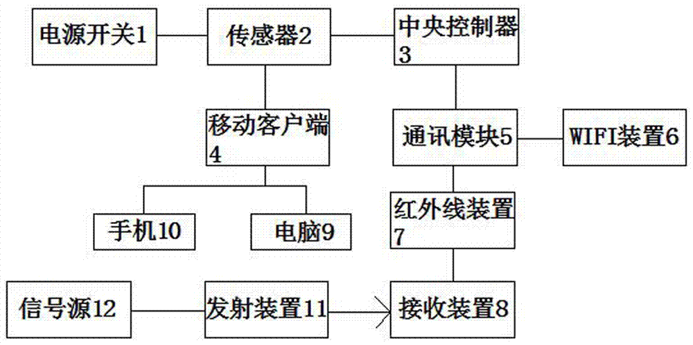
[0024] An infrared control power switch system, including a power switch 1, a sensor 2, a central controller 3 and a communication module 5, the communication module 5 is provided with an infrared device 7, the power switch 1 is connected to a sensor 2, and the sensor 2 monitors the operation of the power switch 1 situation, the sensor 2 is connected with the central controller 3, and the operation of the sensor 2 is controlled by the central controller 3. The central controller 3 is provided with a control program that has been edited. The infrared device 7 receives instructions to activate the program operation of the central controller 3 .

[0025] The sensor 2 is also connected to the mobile client 4, and transmits the monitored status information of the power switch 1 to the mobile client 4, which is conducive to saving the information, and can check the status of the power switch 1 at any time.

[0026] The mobile client 4 is a mobile phone 10 or a computer 9, which is c...

Embodiment 2

[0033] An infrared control power switch system, including a power switch 1, a sensor 2, a central controller 3 and a communication module 5, the communication module 5 is provided with an infrared device 7, the power switch 1 is connected to a sensor 2, and the sensor 2 monitors the operation of the power switch 1 situation, the sensor 2 is connected with the central controller 3, and the operation of the sensor 2 is controlled by the central controller 3. The central controller 3 is provided with a control program that has been edited. The infrared device 7 receives instructions to activate the program operation of the central controller 3 .

[0034] The sensor 2 is also connected to the mobile client 4, and transmits the monitored status information of the power switch 1 to the mobile client 4, which is conducive to saving the information, and can check the status of the power switch 1 at any time.

[0035] The mobile client 4 is a mobile phone 10 or a computer 9, which is c...

Embodiment 3

[0041] An infrared control power switch system, including a power switch 1, a sensor 2, a central controller 3 and a communication module 5, the communication module 5 is provided with an infrared device 7, the power switch 1 is connected to a sensor 2, and the sensor 2 monitors the operation of the power switch 1 situation, the sensor 2 is connected with the central controller 3, and the operation of the sensor 2 is controlled by the central controller 3. The central controller 3 is provided with a control program that has been edited. The infrared device 7 receives instructions to activate the program operation of the central controller 3 .

[0042] The sensor 2 is also connected to the mobile client 4, and transmits the monitored status information of the power switch 1 to the mobile client 4, which is conducive to saving the information, and can check the status of the power switch 1 at any time.

[0043] The communication module 5 is also provided with a WIFI device 6, an...


PUM


Abstract

The invention provides an infrared control power switch system, including a power switch, a sensor, a central controller and a communication module. The communication module is provided with an infrared device. The power switch is connected with the sensor. The sensor monitors the operating status of the power switch. The sensor is connected with the central controller, and the central controller controls the operation of the sensor. The central controller is provided with the programmed control program. The central controller is connected with the communication module and receives instructions from the infrared device of the communication module to activate the program's operation of the central controller. The infrared control power switch system greatly simplifies the operation of the power switch and realizes the working status of the power switch in real time, so that the safety of using the power switch is also greatly improved.

Description

technical field [0001] The invention belongs to the technical field of power switches, and in particular relates to an infrared control power switch system. Background technique [0002] With the rapid development of computer technology and communication technology, more and more high-tech applications have been applied to the fields of electronic police, public security checkpoints, and intelligent transportation, which has improved the technological content, accuracy, and reliability of related systems, and greatly reduced human labor. strength. The normal operation of electronic equipment in various systems in this field is inseparable from the power supply. A reliable and controllable power supply is one of the most important key components for the normal operation of the electronic equipment in the above system. [0003] At present, the indoor 220V power supply of the known technology all adopts a mechanical switch to control the power supply line. Sometimes people fo...

Claims


Application Information

Patent Timeline
Patent Type & Authority Applications(China)
IPC IPC(8): G05B19/04G08C23/04
CPCG05B19/04G08C23/04
Inventor 不公告发明人
Owner HEFEI LIYUANJIE INFORMATION TECH CO LTD
Why Eureka
Try Eureka