Card read-write and transmission system in self-service card receiving machine

A transmission system and card transmission technology, which is applied in the field of card reading and writing and transmission systems, and can solve the problems of slow card transmission, complex structure, and large space occupation

Active Publication Date: 2017-11-07
GUANGZHOU MINGSEN TECH CO LTD
View PDF5 Cites 5 Cited by
  • Summary
  • Abstract
  • Description
  • Claims
  • Application Information

AI Technical Summary

Problems solved by technology

[0004] The shortcomings of the above-mentioned technology: the transmission components of the card feeding mechanism and the card reading mechanism are various, the structur...

Method used


Image

  • Card read-write and transmission system in self-service card receiving machine
  • Card read-write and transmission system in self-service card receiving machine
  • Card read-write and transmission system in self-service card receiving machine

Examples


Embodiment 1

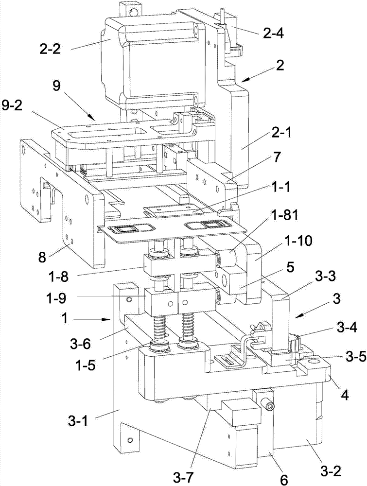
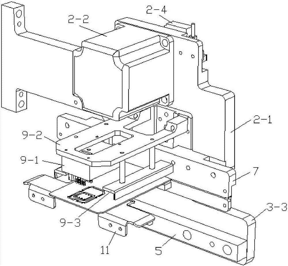
[0044] see Figure 1-6 , the card reading and writing and transmission system in the self-service card receiving machine in the present embodiment includes a card feeding mechanism and a card reading mechanism 9; slot, and a driving mechanism for driving the clamping mechanism 1 to move;

[0045] The clamping mechanism 1 includes a clamping assembly and a clamping drive mechanism that drives the clamping assembly to clamp or loosen the card; the clamping assembly includes an upper clamping part 1-1 and a lower clamping part 1-2 , the upper clamping part 1-1 and the lower clamping part 1-2 are respectively provided with a first clamping part 1-3 and a second clamping part 1-4 at both ends of the extending direction of the card conveying channel, wherein, The first clamping part 1-3 faces the card storage mechanism, and the second clamping part 1-4 faces the card receiving port;

[0046] The drive mechanism includes a horizontal drive mechanism 3 that drives the clamping mecha...

Embodiment 2

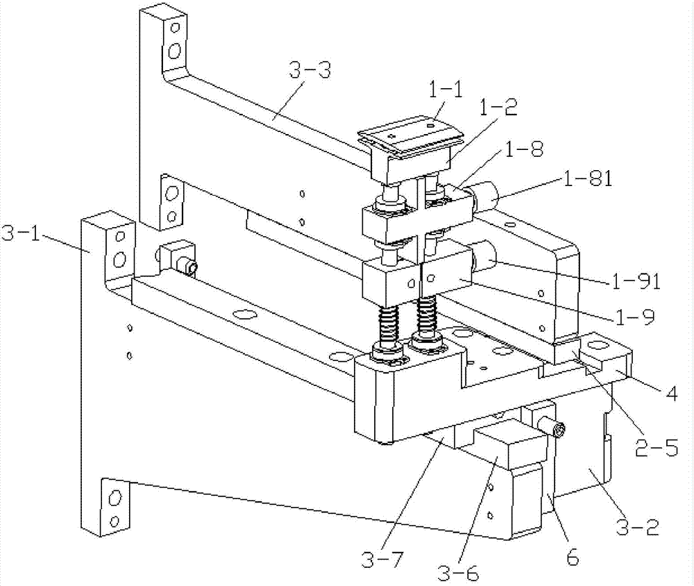
[0075] see Figure 7 , The difference between this embodiment and Embodiment 1 is that in this embodiment, the clamping drive mechanism includes a clamping shaft 1-5, a cylinder 1-12, and an external clamping shaft 1-5. The fixed sleeve 1-11, the upper end of the clamping shaft 1-5 is fixedly connected to the upper clamping member 1-1, the lower end is fixed on the cylinder 1-12, and the fixed sleeve 1-11 is set on the clamping On the outer side of the shaft 1-5, the upper end of the fixed sleeve 1-11 acts on the lower clamping part 1-2, and the lower end acts on the cylinder 1-12; a fixed connection block 4 is provided below the cylinder 1-12 One end of the fixed connection block 4 is connected with the transverse drive mechanism 3, and the other end is fixedly connected with the cylinder 1-12. The working principle of the above-mentioned clamping drive mechanism is: when the card needs to be clamped, the cylinder 1-12 drives the clamping shaft 1-5 to move downward, so that ...


PUM


Abstract

The invention provides a card read-write and transmission system in a self-service card receiving machine. The system comprises a card feeding mechanism and a card reading mechanism. The card feeding mechanism comprises a card clipping mechanism, a card guide slot, and a driving mechanism which is used for driving the card clipping mechanism to move. The card clipping mechanism comprises a clamping assembly and a clamping driving mechanism which is used for driving the clamping assembly to clamp or release. The clamping assembly comprises an upper clamping member and a lower clamping member. A first clamping part and a second clamping part are arranged on the upper clamping member and the lower clamping member respectively. The driving mechanism comprises a transverse driving mechanism and a vertical driving mechanism. The card read-write and transmission system in the self-service card receiving machine can quickly and accurately send an identified card to the corresponding location of a card storage mechanism and a card receiving port. The card reading mechanism is combined with the card clipping mechanism, which reduces the components of the card reading mechanism. The structure of the entire self-service card receiving machine is simple. The manufacturing cost is reduced. The card transmission efficiency is improved.

Description

technical field [0001] The invention relates to a card collection device, in particular to a card reading, writing and transmission system in a self-service card collection machine. Background technique [0002] The self-service card collection machine is an automatic card-issuing device, through which users can self-receive the card made by the card issuer with their ID card and other information. Compared with the traditional manual card issuance procedure, the user's card collection is faster and time More freedom, the card issuer can also save a lot of manpower and material resources. After the card issuing unit (such as a bank) has finished making the card, according to the principle of receiving the card nearby, the card of the user in a specific area is manually stored in the card storage device of the designated self-service card receiving machine; when the user needs to withdraw the card At this time, the self-service card receiving machine first verifies the user'...

Claims


Application Information

Patent Timeline
IPC IPC(8): G06K13/103G06K13/12G06K7/10
CPCG06K7/10415G06K13/103G06K13/12
Inventor 吴伟文李南彪黄文豪周逛
Owner GUANGZHOU MINGSEN TECH CO LTD
Why Eureka
Try Eureka