Feeding device and feeding method of saw cutting machine

A technology of sawing machine and material pushing device, which is applied in metal processing and other directions, which can solve the problems of high difficulty in feeding double pipes, inability to ensure pipe materials, and low efficiency, and achieve the effects of saving time, facilitating material turning, and improving efficiency

Active Publication Date: 2017-11-10
SUZHOU KINKALTECK MACHINERY TECH
View PDF7 Cites 12 Cited by
  • Summary
  • Abstract
  • Description
  • Claims
  • Application Information

AI Technical Summary

Problems solved by technology

[0002] The cutting of circular metal pipes is a commonly used process in many technical fields, and the cutting of a single circular pipe is very mature, but there are some technical problems in the feeding of the current sawing machine: 1. The loading of the current sawing machine The materials are all loaded by pinching. After the pipe is sent from the material rack to the conveying platform, the feeding clamp first clamps the pipe and then moves longitudinally, so that the pipe enters the sawing head for sawing. When a pipe is sawed After that, the feeding clamp is reset to clamp the next pipe. This feeding method is very inefficient, and it is necessary to wait for the sawing of the pipe to be completed before loading a pipe.
2. At present, only one pipe can be loaded in general, and the difficulty of loading double pipes is relatively high. It is impossible to ensure that two pipes are loaded from the material rack to the delivery platform each time.

Method used


Image

  • Feeding device and feeding method of saw cutting machine
  • Feeding device and feeding method of saw cutting machine
  • Feeding device and feeding method of saw cutting machine

Examples


Embodiment Construction

[0040] The present invention will be described in further detail below through specific examples.

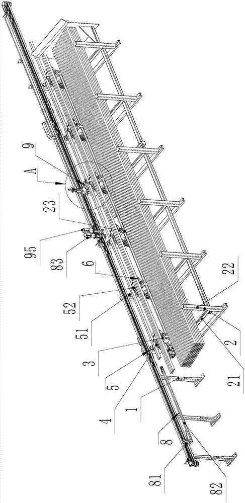
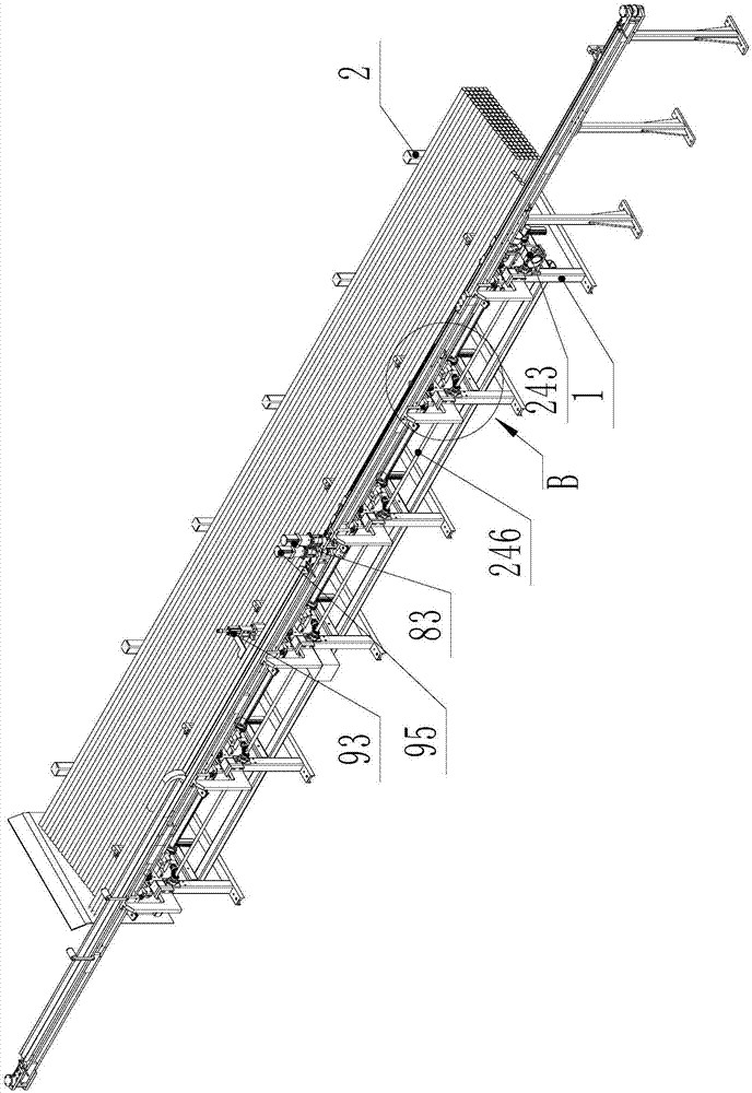
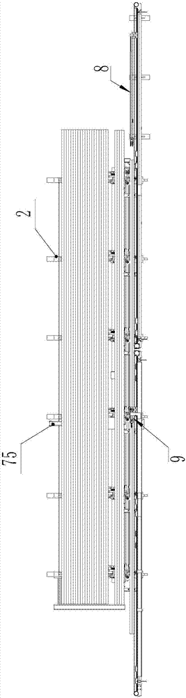
[0041] like Figure 1 to Figure 9 As shown, a feeding device of a sawing machine includes a frame 1, which is installed and supported as a part of the entire feeding device, and is a frame structure.

[0042] like Figure 4 As shown, the frame 1 is provided with a material rack 2 for stacking pipes, the bottom of the material frame 2 is inclined, and the material frame 2 includes several inclined bottom beams 21 installed on the frame 1 , the high end of each bottom beam 21 is fixed with a fixed gear rod 22, and several sliding gear rods 23 are horizontally slidably installed on the frame 1, and the fixed gear rod 22, the bottom beam 21 and the sliding gear rod 23 constitute a groove-shaped area , the pipes are stacked in the trough-shaped area, and each sliding bar 23 is adjusted 24 by the same horizontal adjustment device, and the position of the sliding bar 23 is located at...


PUM


Abstract

The invention discloses a feeding device and feeding method of a saw cutting machine. The feeding device includes a rack, a material frame, a material storage platform, a material squeezing mechanism, a conveying platform, a limiting assembly and a material turning mechanism; the rack is provided with a first material pushing device and a second material pushing device in a sliding mode in the longitudinal direction, a first material pushing rod is used for pushing pipe materials to a first limiting position in the longitudinal direction, a second first material pushing rod is used for pushing pipe materials at the first limiting position to a second limiting position, the upstream end portions of the pipe materials located on the first limiting position are conveniently cooperated with the second material pushing rod, and upstream end portions of the pipe materials located on the second limiting position are located on the downstream position of the downstream end portion of the pipe materials on the material storage platform. The feeding device can achieve rapid feeding of the pipe materials and greatly improve the efficiency of feeding. The feeding method can greatly improve the feeding efficiency by using the feeding device.

Description

technical field [0001] The invention relates to a feeding device of a sawing machine, and also relates to a feeding method using the feeding device. Background technique [0002] The cutting of circular metal pipes is a commonly used process in many technical fields, and the cutting of a single circular pipe is very mature, but there are some technical problems in the feeding of the current sawing machine: 1. The loading of the current sawing machine The material is fed by pinch feeding. After the pipe is sent from the material rack to the conveying platform, the feeding clamp first clamps the pipe and then moves longitudinally, so that the pipe enters the sawing head for sawing. When a pipe is sawed Finally, the feeding clamp is reset to clamp the next pipe. This feeding method is very inefficient, and it is necessary to wait for the sawing of the pipe to be completed before loading a pipe. 2. At present, only one pipe can be loaded in general, and the difficulty of loadin...

Claims


Application Information

Patent Timeline
Patent Type & Authority Applications(China)
IPC IPC(8): B23Q7/00B23Q7/10B23Q7/06
CPCB23Q7/00B23Q7/005B23Q7/06B23Q7/10Y02P70/10
Inventor 李全军柯晓华
Owner SUZHOU KINKALTECK MACHINERY TECH
Why Eureka
Try Eureka