
Brake disc DTV repairing machine

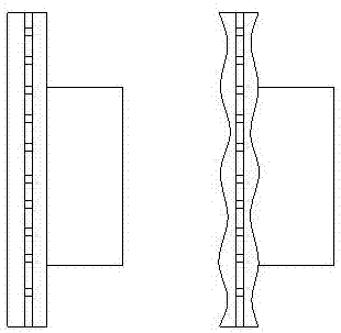
A brake disc and repairing machine technology, which is applied in the direction of manufacturing tools, grinding drive devices, and grinding machine parts, etc., can solve the problems of narrow use range, large customer complaints, and many parts, and achieve the effect of convenient control

Active Publication Date: 2017-11-10
CHERY AUTOMOBILE CO LTD
View PDF10 Cites 3 Cited by
  • Summary
  • Abstract
  • Description
  • Claims
  • Application Information

AI Technical Summary

Problems solved by technology

For the situation that the DTV of the brake disc is out of tolerance, the current practice is: 1. Directly replace the new brake disc, which is very expensive, and the customer complains a lot, and the supplier complains a lot; the management cost and labor cost of after-sales spare parts are relatively high. high
2. On-line repair. At present, there are mainly repair machines from Toyota, which adopt the turning method. The brake disc is driven by an external motor to rotate, and the turning tools on both sides of the working surface are fed separately. The main disadvantages of turning repair are low turning precision, difficulty in ensuring the plane and contour of the working surface of the brake disc, complex equipment, many parts, high cost, and narrow application range. In addition, the turning feed control is complicated. The two sides of the brake disc need to be fed separately. If the cutting force is inconsistent on both sides, it is easy to cause extra bending moment of the mechanism and repair deviation

Method used


Image

  • Brake disc DTV repairing machine
  • Brake disc DTV repairing machine
  • Brake disc DTV repairing machine

Examples


Embodiment 1

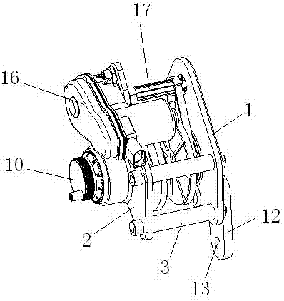
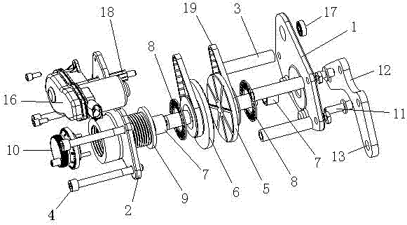
[0030] As shown in the figure, the brake disc DTV repairing machine of this embodiment includes an inner plate 1 and an outer plate 2. The inner plate 1 and the outer plate 2 are provided with three through holes corresponding to the positions. A support sleeve 3 is clamped at the position of the through hole, and they are fixedly connected together by fastening bolts 4 passing through the outer plate 2 , the support sleeve 3 and the inner plate 1 in sequence. A first grinding wheel 5 and a second grinding wheel 6 are installed between the inner plate 1 and the outer plate 2. The inner plate 1 is provided with a limiting hole, and a copper sleeve 7 is installed in the limiting hole. The rotating shaft of the first grinding wheel 5 Extending into the copper sleeve 7, the inner plate 1 is offset against the first grinding wheel 5 through the end face bearing 8, so that the first grinding wheel 5 is flexibly connected with the inner plate 1; the outer plate 2 is provided with a fe...


PUM


Abstract

The invention aims at providing a brake disc DTV repairing machine which is simple in structure, convenient to operate, low in cost and good in universality. The brake disc DTV repairing machine comprises an inner plate and an outer plate which are fixedly connected. Two opposite grinding wheels are arranged between the inner plate and the outer plate. The first grinding wheel is movably connected with the inner plate, the outer plate is provided with a feeding propelling nut through thread matching, and the second grinding wheel is movably connected with the feeding propelling nut; the inner plate is movably connected with a connection support through guide pins, and the inner plate can move relative to the connection support in the axis direction of grinding wheel rotation shafts; and the connection support is provided with a connection mechanism which is used for being movably connected with a brake disc to be repaired. The brake disc DTV repairing machine is further provided with a drive assembly. A drive shaft of the drive assembly is connected with the rotation shafts of the first grinding wheel and the second grinding wheel through belts. The drive shaft of the drive assembly is provided with a drive segment with a preset length so that driving to the first grinding wheel and the second grinding wheel can be guaranteed when the first grinding wheel and the second grinding wheel move relative to the drive assembly.

Description

technical field [0001] The invention belongs to the technical field of auto parts maintenance, and in particular relates to a repairing device for a brake disc. Background technique [0002] With the gradual expansion of the passenger car market, the comfort of the vehicle during use has been paid more and more attention by customers. Some vehicles experience vehicle vibration during braking, which seriously affects comfort. 80% of the above vibration is caused by the uneven thickness of the brake disc in the circumferential direction (that is, DTV, Disc thickness variation). For the situation that the DTV of the brake disc is out of tolerance, the current practice is: 1. Directly replace the new brake disc, which is very expensive, and the customer complains a lot, and the supplier complains a lot; the management cost and labor cost of after-sales spare parts are relatively high. high. 2. On-line repair. At present, there are mainly repair machines from Toyota, which adop...

Claims


Application Information

Patent Timeline
IPC IPC(8): B24B7/17B24B41/06B24B47/20
CPCB24B7/17B24B41/06B24B47/203
Inventor 李成刘泉李彬
Owner CHERY AUTOMOBILE CO LTD
Learn More