Machining method for plasma-sprayed surface of internal annular surface of annular housing

A processing method and plasma technology, applied in the direction of blade support components, engine components, machines/engines, etc., can solve the problems of inaccurate control of machining allowance, easy deviation of machining results, and inability to measure and control the diameter of the contour.

Active Publication Date: 2014-02-05
CHINA HANGFA SOUTH IND CO LTD
View PDF4 Cites 0 Cited by
  • Summary
  • Abstract
  • Description
  • Claims
  • Application Information

AI Technical Summary

Problems solved by technology

[0003] The general processing method of the annular cover is to indirectly guarantee the surface profile and runout requirements through the size of the part base, but the part base material is a nickel-based alloy, which has a different machining performance from the plasma sprayed material. There is a tool gap, and the sprayed profile and the inner hole of the part are processed by the same tool at one time. The machining allowance and tool compensation are determined by measuring the diameter of the inner hole, which indirectly guarantees the profile and runout requirements. The indirect control method is subject to The influence of the difference in machining performance can easily lead to inaccurate control of machining allowance, resulting in out-of-tolerance spraying profile and runout
[0004] That is to say, the existing annular housing has high requirements on the contour of the plasma sprayed surface. The machining performance of the plasma sprayed material and the base material of the part is different, and the profile cannot be controlled by diameter measurement. Instead, the spraying is indirectly controlled by measuring the size of the base of the part. The profile of the profile, the processing result is prone to deviation

Method used


Image

  • Machining method for plasma-sprayed surface of internal annular surface of annular housing
  • Machining method for plasma-sprayed surface of internal annular surface of annular housing
  • Machining method for plasma-sprayed surface of internal annular surface of annular housing

Examples


Embodiment Construction

[0019] In order to have a clearer understanding of the technical features, purposes and effects of the present invention, the specific implementation manners of the present invention will now be described with reference to the accompanying drawings. Wherein, the same parts adopt the same reference numerals.

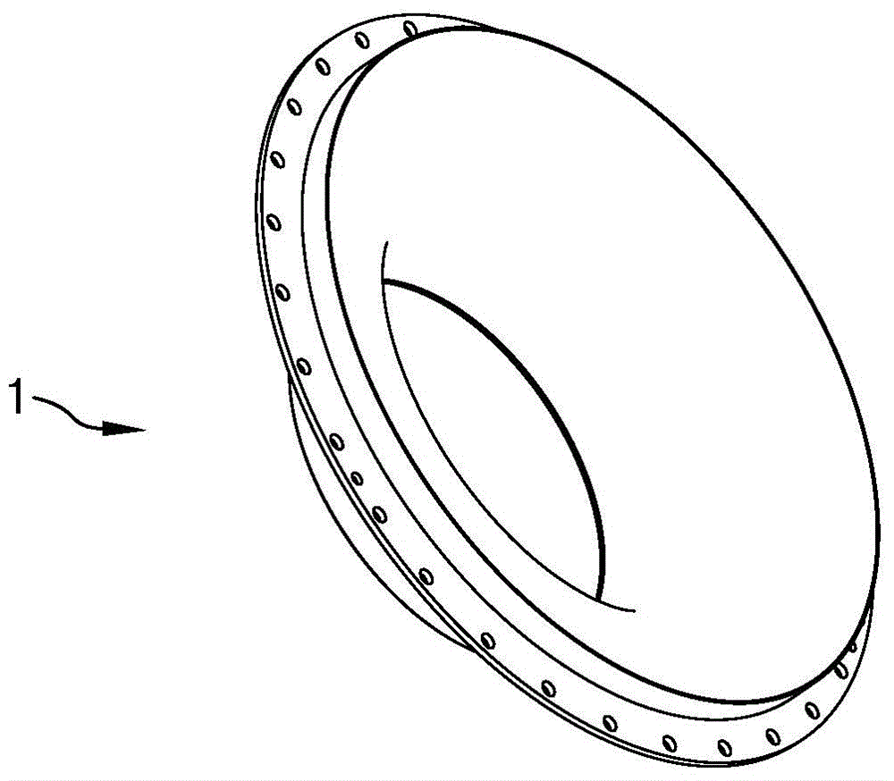
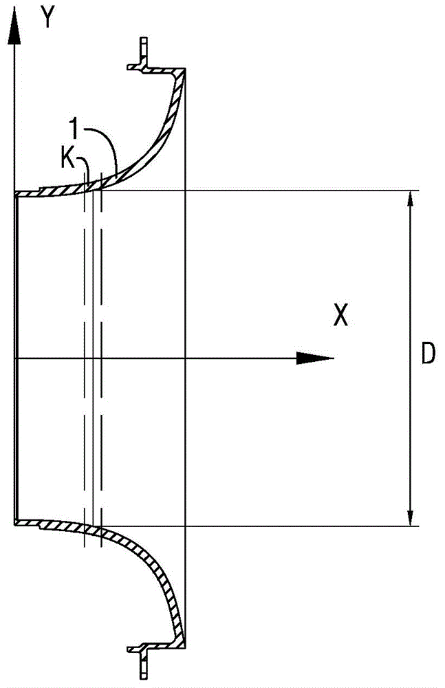
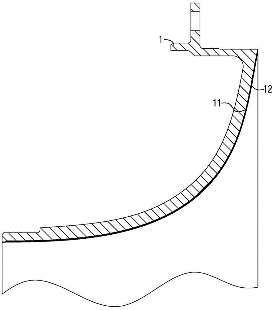
[0020] figure 2 Shown is figure 1 The cross-sectional view of the shown annular housing 1, image 3 Shown is figure 2 An enlarged view of the upper half of the cross-sectional view, as described in the background section, figure 2 , 3 The annular housing 1 may be an impeller housing for an aero-engine, and the base material of the annular housing 1 is a nickel-based alloy. Such as image 3 As shown, during processing, first use the base material to manufacture the green body of the annular outer cover 1 by ordinary mechanical processing means, and then spray a layer of plasma material 12 on the inner ring surface 11 of the green body, and the plasma spraying mate...


PUM

PropertyMeasurementUnit
thicknessaaaaaaaaaa
thicknessaaaaaaaaaa
diameteraaaaaaaaaa

Abstract

A machining method for the plasma-sprayed surface of the internal annular surface of an annular housing is used for finishing the plasma-sprayed surface of the internal annular surface of the annular housing sprayed with plasma spraying material. The method includes the following steps: along the axial direction of the annular housing, the annular housing is divided into a plurality of continuous annular blocks, and the actual measured diameter of the plasma-sprayed surface of the internal annular surface of each annular block is measured; a spline curve is constructed for the actual measured diameters meeting design requirements, machining allowances are determined by using machining diameters measured on the spline curve, finally, the machining allowance corresponding to each annular block is set into a numerically controlled machine tool, the numerically controlled machine tool is utilized to remove the machining allowance of each annular block, so that the machined annular housing is obtained, and thereby the profile tolerance of the plasma-sprayed surface of the internal annular surface of the annular housing can meet the design requirements.

Description

technical field [0001] The invention relates to a processing method of aviation parts, in particular to a processing method of impeller casing parts of an aero-engine, in particular to a processing method of plasma spraying the inner ring surface of an annular casing. Background technique [0002] The annular housing of the impeller housing is a common part in the aero-engine system. figure 1 It shows a three-dimensional structural schematic diagram of a typical impeller housing annular housing 1, the inner ring surface of the annular housing 1 needs to be plasma sprayed to form a layer of plasma sprayed material thereon to increase its hardness and wear resistance. The base material of the annular outer cover is nickel-based alloy, and the plasma spraying material is aluminum alloy-boron nitride abradable powder (composition: silicon, boron nitride, aluminum, organic solid). [0003] The general processing method of the annular cover is to indirectly guarantee the surface ...

Claims


Application Information

Patent Timeline
Patent Type & Authority Applications(China)
IPC IPC(8): B23P15/00
CPCB23P15/00F01D5/286
Inventor 梁聪鄢勤
Owner CHINA HANGFA SOUTH IND CO LTD
Why Eureka
Try Eureka