Hydraulic time difference brake device and its assembly
A brake device, hydraulic technology, applied to bicycle accessories, bicycle brakes, etc., can solve problems such as vehicle tail drifting and crash accidents, and achieve the effect of improving braking efficiency and safety
- Summary
- Abstract
- Description
- Claims
- Application Information
AI Technical Summary
Problems solved by technology
Method used
Image
Examples
Embodiment Construction
[0031] In order for examiners to further understand the hydraulic time difference brake device of the present invention, the best implementation is explained as follows with reference to the accompanying drawings:
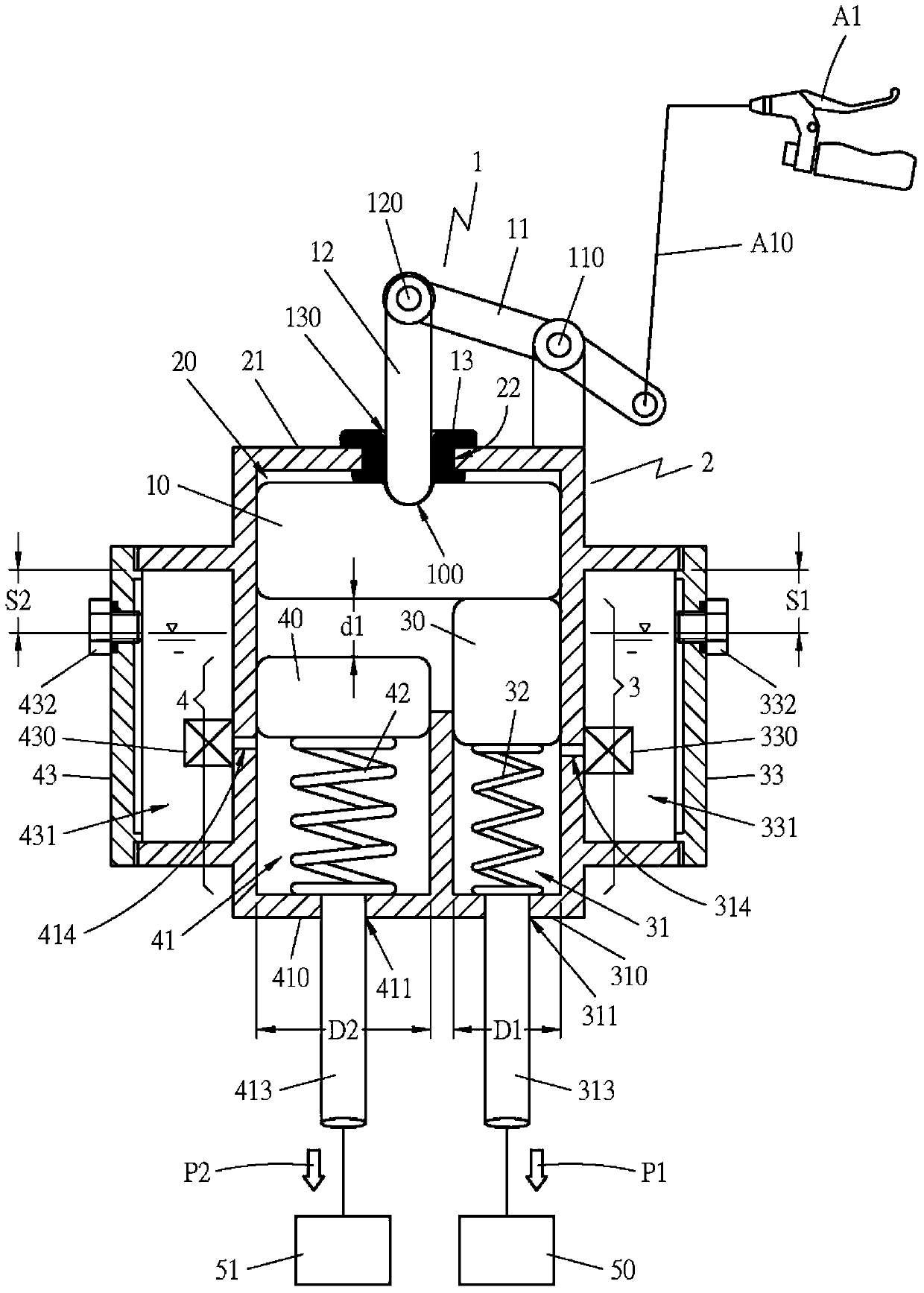
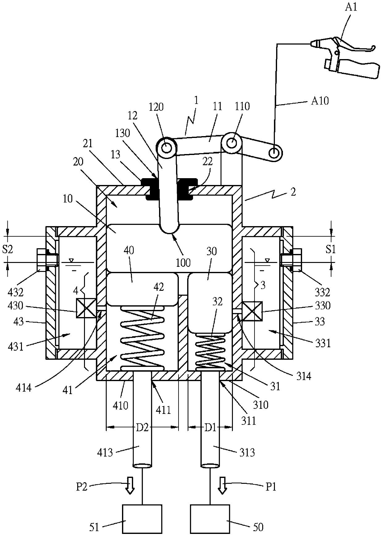
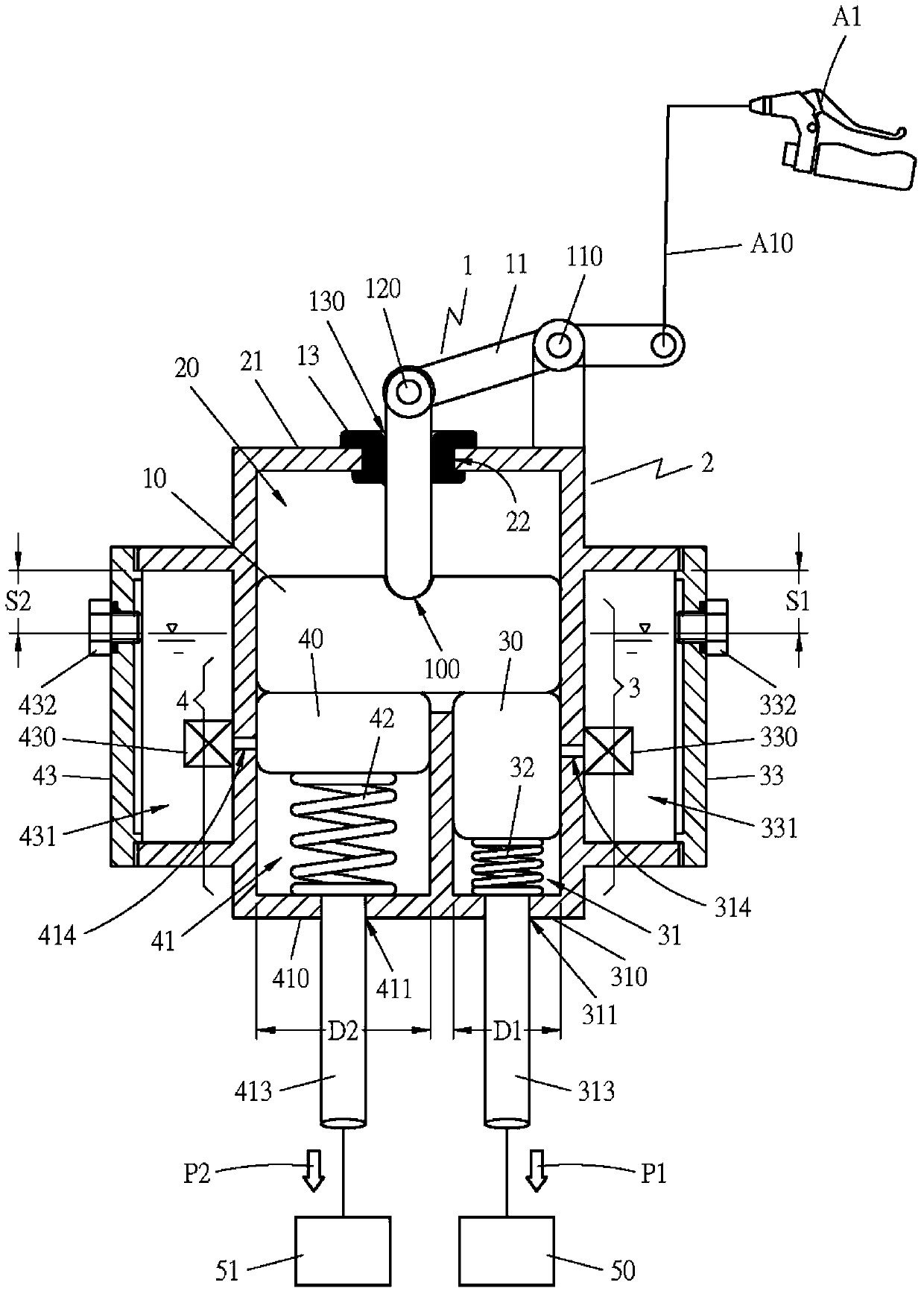
[0032] Such as Figure 1~3 , the hydraulic time difference braking device of the present invention at least includes: a driving mechanism 1, which is linked with the brake operation assembly A1, the aforementioned driving mechanism 1 is provided with a push block 10, which is arranged on the top of the chamber 20 of the casing 2, and A coupling groove 100 is provided at the center of the push block 10 to facilitate coupling with the driving rod 12 . The aforementioned driving mechanism 1 is provided with a lever 11 again, and the lever 11 is provided with a fulcrum 110. The aforementioned lever 11 is located at one end of the fulcrum 110 and is combined with the cable line A10 of the brake operating assembly A1. 12 are mutually combined into movable fulcrum 120. ...
PUM
 Abstract
Description
Claims
Application Information
 - R&D
- Intellectual Property
- Life Sciences
- Materials
- Tech Scout
- Unparalleled Data Quality
- Higher Quality Content
- 60% Fewer Hallucinations
Browse by: Latest US Patents, China's latest patents, Technical Efficacy Thesaurus, Application Domain, Technology Topic, Popular Technical Reports.
© 2025 PatSnap. All rights reserved.Legal|Privacy policy|Modern Slavery Act Transparency Statement|Sitemap|About US| Contact US: help@patsnap.com


