Antenna structure and mobile terminal

An antenna structure and mobile terminal technology, applied in the field of communication, can solve the problems of poor antenna communication effect and the like

Active Publication Date: 2017-11-17
VIVO MOBILE COMM CO LTD
View PDF4 Cites 21 Cited by
  • Summary
  • Abstract
  • Description
  • Claims
  • Application Information

AI Technical Summary

Problems solved by technology

[0003] The embodiment of the present invention provides an antenna structure and a mobile terminal to solve the problem of poor communication effect of existing antennas

Method used


Image

  • Antenna structure and mobile terminal
  • Antenna structure and mobile terminal
  • Antenna structure and mobile terminal

Examples


Embodiment Construction

[0013] The following will clearly and completely describe the technical solutions in the embodiments of the present invention with reference to the accompanying drawings in the embodiments of the present invention. Obviously, the described embodiments are some of the embodiments of the present invention, but not all of them. Based on the embodiments of the present invention, all other embodiments obtained by persons of ordinary skill in the art without creative efforts fall within the protection scope of the present invention.

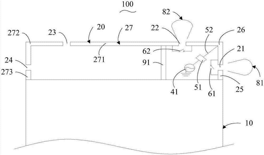
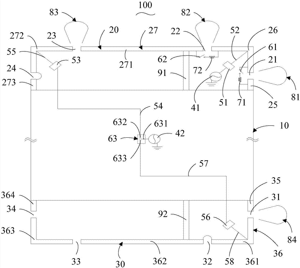
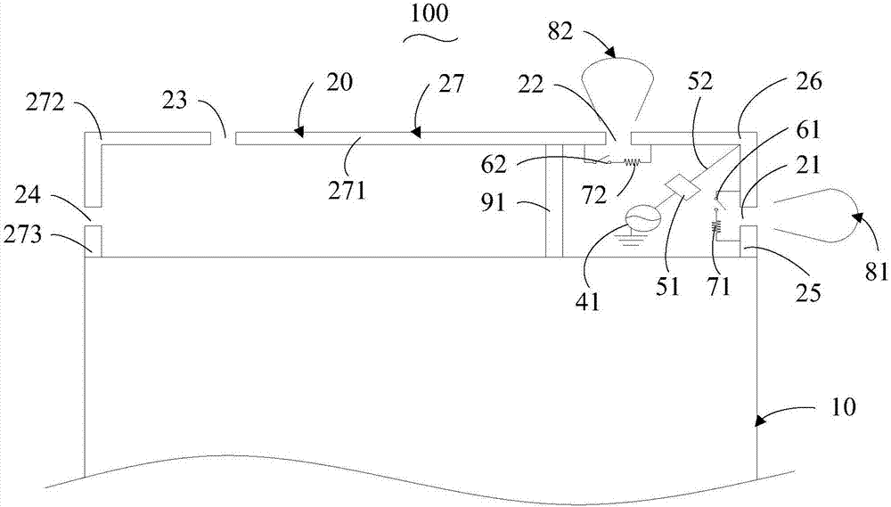
[0014] In the current antenna structure, the best radiation direction of the antenna structure, that is, the best direction of the communication signal, is the direction where the fracture of the metal radiation frame in the antenna structure is located.

[0015] see Figure 1 to Figure 3 , figure 1 is one of the structural schematic diagrams of the antenna structure provided by the embodiment of the present invention; figure 2 It is the second stru...


PUM


Abstract

The invention provides an antenna structure and a mobile terminal. The antenna structure at least comprises a first metal radiation frame, a first antenna feed source and a first antenna matching circuit; the first metal radiation frame is arranged at one end of a metal back shell; a first fracture opening and a second fracture opening are formed in the first metal radiation frame; a first switch and a second switch are arranged corresponding to the first fracture opening and the second fracture opening; the first switch and the second switch are in a switched-on or switched-off state according to the posture of the mobile terminal, and the first fracture opening and the second fracture opening are formed in the adjacent side of the first metal radiation frame; the first end of the first antenna feed source is grounded and the second end of the first antenna feed source is connected with the first end of the first antenna matching circuit; and the second end of the first antenna matching circuit is connected with the first metal radiation frame. Therefore, the optimal radiation direction of the antenna structure can be adjusted by changing the fracture opening positions of the antenna structure according to the posture of the mobile terminal, thereby maintaining the communication effect of the antenna structure at a high state.

Description

technical field [0001] The present invention relates to the technical field of communications, in particular to an antenna structure and a mobile terminal. Background technique [0002] At present, most mobile terminals have antennas for wireless communication, such as a positioning antenna that can realize the positioning function of the mobile terminal, and the positioning function of the mobile terminal is achieved through the communication between the positioning antenna installed on the mobile terminal and the satellite. Achieved. Usually, each mobile terminal is equipped with only one positioning antenna, and the radiation pattern of each positioning antenna is fixed and non-adjustable, so that the optimal radiation direction of the positioning antenna is fixed. Moreover, due to the popularization and application of mobile terminals, there are more and more usage scenarios of mobile terminals. When the best radiation direction of the positioning antenna of the mobile ...

Claims


Application Information

Patent Timeline
Patent Type & Authority Applications(China)
IPC IPC(8): H01Q1/36H01Q1/50H01Q1/48H01Q1/24
CPCH01Q1/243H01Q1/36H01Q1/48H01Q1/50
Inventor 李东明
Owner VIVO MOBILE COMM CO LTD
Why Eureka
Try Eureka