a prosthetic leg structure

A prosthetic leg and transmission mechanism technology, applied in prosthetics, artificial legs, medical science, etc., can solve the problems of walking gait gap, single knee-ankle angle relationship, and occasions that cannot adapt to active torque, so as to reduce energy consumption , the effect of simplifying the control method

Active Publication Date: 2019-03-08
苏州普瑞川传动科技有限公司
View PDF5 Cites 0 Cited by
  • Summary
  • Abstract
  • Description
  • Claims
  • Application Information

AI Technical Summary

Problems solved by technology

The former is to connect the knee and ankle joints together through a mechanical structure. The two joints can move according to a certain relationship, but this design sacrifices a degree of freedom. The angle relationship between the knee and ankle is single and cannot be changed flexibly. Usually, it is purely mechanical. Structural prosthetics will use this design; the latter's knee joint and ankle joint can move independently and freely on the mechanical structure, and the coupled motion of the knee and ankle is realized by the control system for the joint control of the two joints in accordance with the gait law of normal people. , such a design makes it difficult to control the coordinated control of the knee and ankle joints
[0004] At present, the damping lower limb prosthesis is the mainstream of intelligent lower limb prosthesis. This type of lower limb prosthesis can walk on flat ground, ramps and even stairs, but it cannot adapt to occasions that require active torque. At the same time, the walking gait is still relatively large compared with normal gap

Method used


Image

  • a prosthetic leg structure
  • a prosthetic leg structure
  • a prosthetic leg structure

Examples


Embodiment Construction

[0038] The specific implementation manners of the present invention will be further described in detail below in conjunction with the accompanying drawings and embodiments. The following examples are used to illustrate the present invention, but are not intended to limit the scope of the present invention.

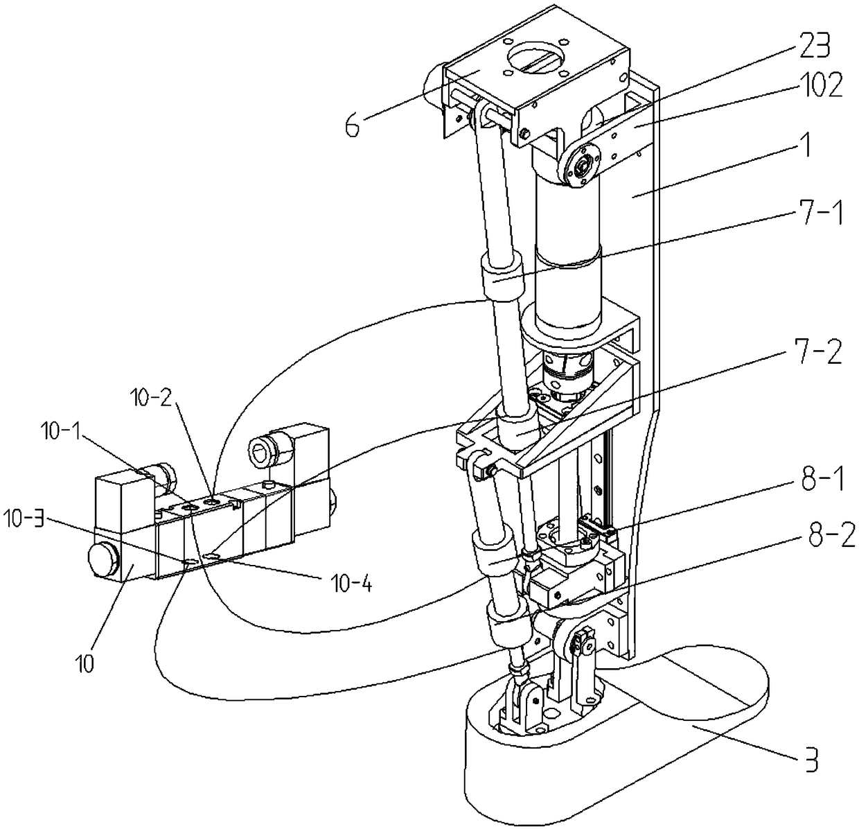
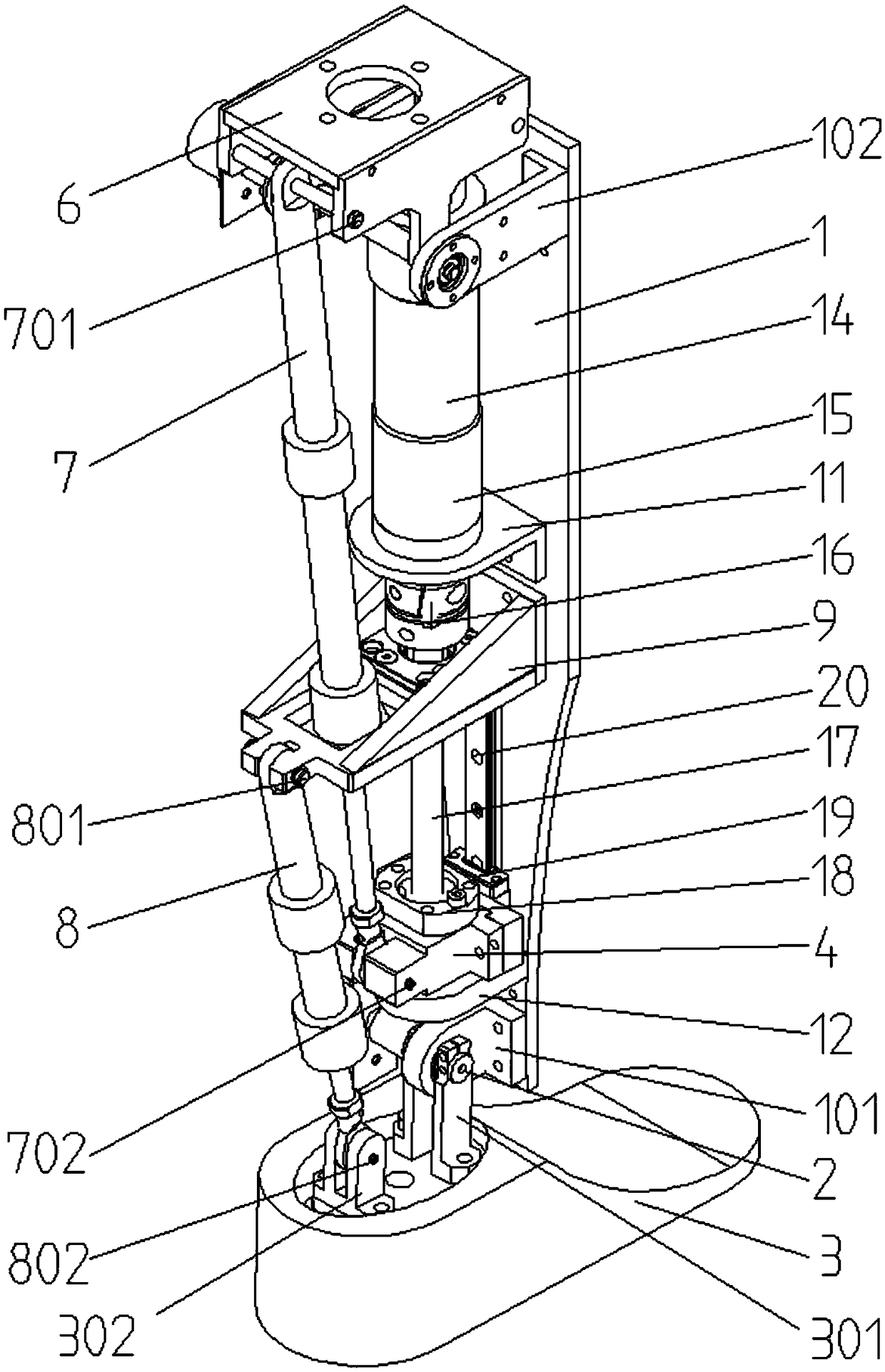
[0039] see figure 1 and Figure 7, a prosthetic leg structure according to a preferred embodiment of the present invention, comprising a base plate 1 for installing most parts, a foot plate 3 that is rotationally connected with the base plate 1 through a first rotating shaft 2, placed on the base plate 1 on the drive mechanism. In this embodiment, the preferred connection mode between the foot plate and the base plate is as follows: set the foot plate support seat 301 on the foot plate, set the ankle joint support seat 101 on the base plate, and pass between the ankle joint support seat 101 and the foot plate support seat 301 through a first The rotating shaft 2 is conn...


PUM


Abstract

The invention relates to a prosthetic leg structure, which includes a base plate, a foot plate rotatably connected to the base plate through a first rotating shaft, and a driving mechanism placed on the base plate. The driving mechanism includes a moving part that moves up and down along the base plate. An adapter block is rotatably connected, and the prosthetic leg structure also includes a first transmission mechanism and a second transmission mechanism. The moving part is rotatably connected, the upper end of the second transmission mechanism is rotatably connected with the first support base provided on the base plate through the third axis, and the lower end of the second transmission mechanism is rotatably connected with the foot plate through the fourth axis. In the present application, the drive mechanism and the transmission mechanism are provided at the same time to realize active and passive hybrid driving of the lower limb prosthesis, and to achieve different gait control effects.

Description

technical field [0001] The invention belongs to the technical field of rehabilitation medical equipment, and in particular relates to an artificial leg structure. Background technique [0002] According to the second national sample survey of disabled persons, the types and total number of disabled persons in my country are huge, accounting for 6.34% of the total population of the country. Among them, physical disabilities accounted for 29.07%, ranking first among all types of disabilities. Among them, there are about 2.26 million amputees, accounting for 8% of the disabled. At the same time, among the 2.26 million amputees, about 1.5 million can be fitted with artificial limbs, and 630,000 people urgently need to be fitted with artificial limbs, of which 70% are lower limb amputee. Therefore, the popularization and installation of lower limb artificial limbs is currently the basic need for amputees. important means. Lower limb prostheses can make up for the limb defects ...

Claims


Application Information

Patent Timeline
Patent Type & Authority Patents(China)
IPC IPC(8): A61F2/60A61F2/70A61F2/66A61F2/74
CPCA61F2/60A61F2/66A61F2/6607A61F2/68A61F2002/6614A61F2002/6827A61F2/74A61F2/748
Inventor 陈敏
Owner 苏州普瑞川传动科技有限公司
Why Eureka
Try Eureka