
Positioning placement device suitable for columnar and spherical parts

A placement device, spherical technology, applied in the direction of transportation and packaging, conveyor objects, etc., can solve the problems of stable shaft parts, inconvenient use of shaft parts, increased production costs, etc.

Inactive Publication Date: 2017-11-21
芜湖挺优机电技术有限公司
View PDF4 Cites 1 Cited by
  • Summary
  • Abstract
  • Description
  • Claims
  • Application Information

AI Technical Summary

Problems solved by technology

[0002] In the machinery production workshop, in the processing of blanks or finished products of shaft parts or cylindrical parts, non-standard tooling specially used to place such parts is required. Currently, such non-standard tooling is simple in structure and generally adopts The structure of welding the left and right stoppers on the bottom plate can achieve the purpose of placing shafts or cylindrical parts, but this structure is not widely applicable, and many shaft parts cannot be placed in non-standard parts due to size restrictions. The tooling is stable, and if you want to match shaft parts of different sizes, you need to prepare multiple sets of tooling, which increases the production cost. At the same time, some shaft parts that are close to spherical or have transitional surfaces are inconvenient to be used with such tooling. , a non-standard tooling with a wide range of application is needed to solve the above problems and reduce production costs

Method used


Image

  • Positioning placement device suitable for columnar and spherical parts
  • Positioning placement device suitable for columnar and spherical parts
  • Positioning placement device suitable for columnar and spherical parts

Examples


Embodiment Construction

[0020] The following will clearly and completely describe the technical solutions in the embodiments of the present invention with reference to the accompanying drawings in the embodiments of the present invention. Obviously, the described embodiments are only some, not all, embodiments of the present invention. Based on the embodiments of the present invention, all other embodiments obtained by persons of ordinary skill in the art without making creative efforts belong to the protection scope of the present invention.

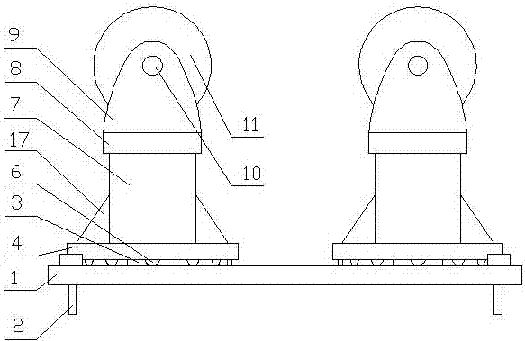
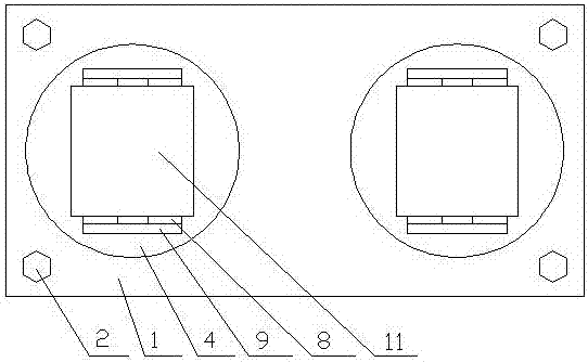
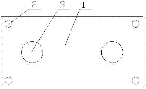
[0021] see Figure 1-9 , the present invention provides a technical solution: a positioning device suitable for cylindrical and spherical components, including a base frame 1, the four corners of the base frame 1 are equipped with anchor bolts 2, the base plate A group of rotating shafts 3 are welded on the frame 1, and the rotating shafts 3 are rotatably matched with the swivel base 4, and a group of bolt shafts 5 are mounted on the outer edge of the swivel s...


PUM


Abstract

The invention discloses a positioning placement device suitable for columnar and spherical parts. The positioning placement device comprises a baseplate frame, wherein foundation bolts are mounted at four corners of the baseplate frame in a penetrating manner; a group of rotating shafts are welded on the baseplate frame; the rotating shafts are in running fit with rotary bases; a group of bolt shafts are mounted at the outer edge of each rotary base in a penetrating manner and are in running fit with rollers; the rollers are in contact with the baseplate frame; an upright is welded with the upper part of each rotary base; a top frame is welded at the top of each upright; pin shaft rack are welded in two side positions of each top frame; the pin shaft racks are matched with rotating rollers through pin shafts; the rotating rollers are in running fit with the corresponding pin shafts; and a rotating shaft groove is formed in the bottom center of the each rotary base. The positioning placement device suitable for the columnar and spherical parts is simple in structure, low in production cost and reliable in positioning with the ground, can be used in group, meets the placement demands of the columnar parts, the spherical parts, and parts with conical faces, and satisfies the requirement for rotating the parts during detection.

Description

technical field [0001] The invention relates to the field of mechanical non-standard tooling, in particular to a positioning and placing device suitable for cylindrical and spherical components. Background technique [0002] In the machinery production workshop, in the processing of blanks or finished products of shaft parts or cylindrical parts, non-standard tooling specially used to place such parts is required. Currently, such non-standard tooling is simple in structure and generally adopts The structure of welding the left and right stoppers on the bottom plate can achieve the purpose of placing shafts or cylindrical parts, but this structure is not widely applicable, and many shaft parts cannot be placed in non-standard parts due to size restrictions. The tooling is stable, and if you want to match shaft parts of different sizes, you need to prepare multiple sets of tooling, which increases the production cost. At the same time, some shaft parts that are close to spheri...

Claims


Application Information

Patent Timeline
Patent Type & Authority Applications(China)
IPC IPC(8): B65G47/74
CPCB65G47/74
Inventor 仝童
Owner 芜湖挺优机电技术有限公司
Learn More