Channel state information measurement method and device
A channel state information and measurement method technology, applied in the field of channel state information measurement methods and devices, can solve the problems of low channel state information measurement efficiency and the like
- Summary
- Abstract
- Description
- Claims
- Application Information
AI Technical Summary
Problems solved by technology
Method used
Image

Examples
Embodiment 1
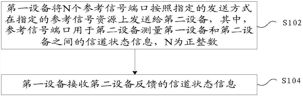
[0099] In this embodiment, a method for measuring channel state information is provided, figure 1 is a flowchart of a method for measuring channel state information according to an embodiment of the present invention, such as figure 1 As shown, the process includes the following steps:
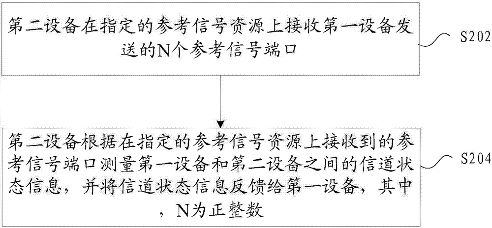
[0100] Step S102, the first device sends N reference signal ports to the second device on designated reference signal resources according to a designated transmission method, wherein the reference signal ports are used by the second device to measure the distance between the first device and the second device The channel state information of , N is a positive integer;
[0101] Step S104, the first device receives channel state information fed back by the second device.
[0102] Wherein, the N reference signal ports are used by the second device to measure channel state information between the first device and the second device, and N is a positive integer.
[0103] Through the above steps, ...
Embodiment 2
[0143] In this embodiment, a device for measuring channel state information is also provided, and the device is used to implement the above embodiments and preferred implementation modes, and those that have been explained will not be repeated here. As used below, the term "module" may be a combination of software and / or hardware that realizes a predetermined function. Although the devices described in the following embodiments are preferably implemented in software, implementations in hardware, or a combination of software and hardware are also possible and contemplated.
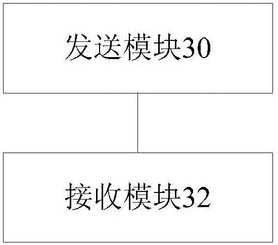
[0144] image 3 is a structural block diagram of a device for measuring channel state information according to an embodiment of the present invention, which can be set at the sending end or the base station side, such as image 3 As shown, the device includes:
[0145] The sending module 30 is configured to send the N reference signal ports of the first device to the second device on designated reference ...
Embodiment 3
[0183] This embodiment is an optional embodiment, and includes multiple specific embodiments, which are used to describe and explain the foregoing embodiments in detail.
PUM
 Abstract
Description
Claims
Application Information
 - R&D
- Intellectual Property
- Life Sciences
- Materials
- Tech Scout
- Unparalleled Data Quality
- Higher Quality Content
- 60% Fewer Hallucinations
Browse by: Latest US Patents, China's latest patents, Technical Efficacy Thesaurus, Application Domain, Technology Topic, Popular Technical Reports.
© 2025 PatSnap. All rights reserved.Legal|Privacy policy|Modern Slavery Act Transparency Statement|Sitemap|About US| Contact US: help@patsnap.com