Signal transmission method and device and user equipment

A technology of signal transmission and symbol position, applied in the field of communication, can solve problems such as obtaining channel information feedback and difficulties in base stations

Active Publication Date: 2017-11-21
ZTE CORP
View PDF11 Cites 12 Cited by
  • Summary
  • Abstract
  • Description
  • Claims
  • Application Information

AI Technical Summary

Problems solved by technology

However, because the LBT result limits downlink signal transmission, it is difficult for the base station to obtain channel information feedback from the UE side in time

Method used


Image

  • Signal transmission method and device and user equipment
  • Signal transmission method and device and user equipment
  • Signal transmission method and device and user equipment

Examples


Embodiment 1

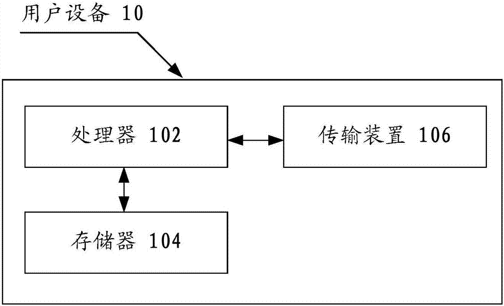
[0109] The method embodiment provided in Embodiment 1 of the present application may be executed in a user equipment, a computer terminal, or a similar computing device. Taking running on user equipment as an example, figure 1 It is a block diagram of a hardware structure of a user equipment of a signal transmission method according to an embodiment of the present invention. Such as figure 1 As shown, the user equipment 10 may include one or more (only one is shown in the figure) processor 102 (the processor 102 may include but not limited to a processing device such as a microprocessor MCU or a programmable logic device FPGA), for A memory 104 for storing data, and a transmission device 106 for communication functions. Those of ordinary skill in the art can understand that, figure 1 The shown structure is only for illustration, and it does not limit the structure of the above-mentioned electronic device. For example, user equipment 10 may also include figure 1 more or fe...

Embodiment 2

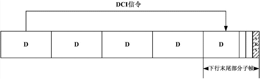
[0249] In this preferred embodiment, a method for instructing UE to transmit SRS in subframes at the end of downlink transmission burst is provided.

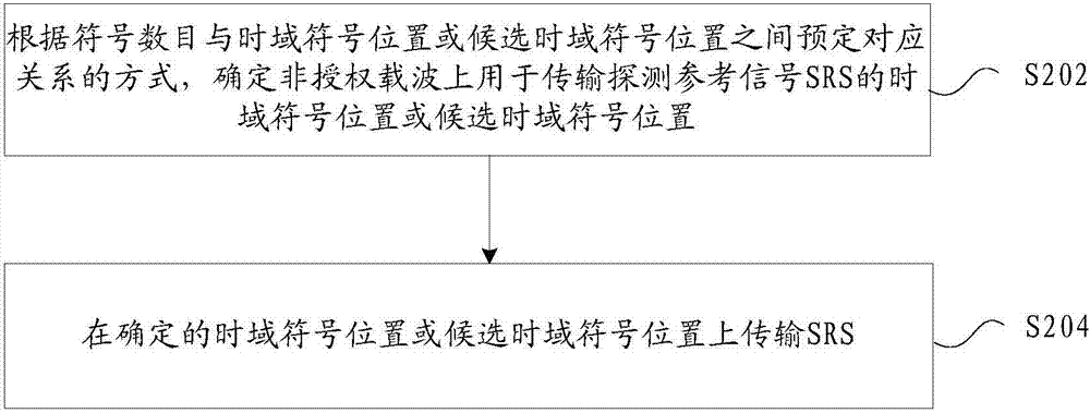
[0250] Specifically in this preferred embodiment, when the user equipment UE performs SRS transmission in the subframe at the end of the downlink transmission burst, the method for determining the time domain symbol position of the SRS transmission, or the candidate time domain symbol position of the SRS transmission includes:

[0251] Method 1: use the corresponding relationship table established between the number of symbols and the time-domain symbol positions of SRS transmission, or the candidate time-domain symbol positions of SRS transmission, and determine the time-domain symbol positions of SRS transmission through the corresponding index number in the table, or, Candidate time-domain symbol positions for SRS transmission.

[0252] in,

[0253] The way to obtain the correspondence table between different numbers of symb...

Embodiment 3

[0363] In this preferred embodiment, a method is provided for different UEs to transmit SRS at different SRS symbol positions, or the same SRS symbol position, or the same candidate SRS symbol position.

[0364] Case 1: For the case where the same SRS symbol position is configured for different UEs, the UE transmits the SRS method.

[0365] For case 1, assuming that there are 6 remaining symbols in the subframe at the end of the downlink transmission burst, the SRS transmission symbol is the last symbol of the remaining 6 symbols (for example, symbol index #13), and the SRS transmission method includes one of the following:

[0366] Method 1: Different UEs perform LBT before the SRS symbol position, and introduce a self-delay mechanism. Wherein, the self-delay may be in the LBT mechanism, or at the end of the LBT mechanism. Figure 8 is a schematic diagram of introducing a self-delay operation into the LBT mechanism when different UEs configure the same time-domain symbol pos...


PUM


Abstract

The invention provides a signal transmission method and device and user equipment. The signal transmission method comprises the steps of determining a time-domain symbol position or a candidate time-domain symbol position used for transmitting a sounding reference signal (SRS) on an unlicensed carrier according to a predetermined corresponding relation between the number of symbols and the time-domain symbol position or the candidate time-domain symbol position; and transmitting the SRS at the determined time-domain symbol position or the candidate time-domain symbol position. According to the invention, a problem of how to improve the transmission opportunity of the SRS in the related art can be solved, and an effect of effectively improving the transmission opportunity of the SRS is achieved.

Description

technical field [0001] The present invention relates to the communication field, and in particular, to a signal transmission method, device, and user equipment (User Equipment, UE for short). Background technique [0002] With the rapid growth of data services, the pressure of data transmission on the carrier of the licensed spectrum is also increasing. Therefore, using unlicensed spectrum carriers to share the data traffic in licensed carriers becomes an important evolution direction in the subsequent development of Long Term Evolution (LTE for short). Among them: unlicensed spectrum has the following characteristics: free / low cost; low access requirements, low cost; large available bandwidth; resource sharing; and so on. [0003] In the standardization research process of Licensed Assisted Access (LAA for short), Sounding Reference Signal (Sounding Reference Signal, SRS for short) is being studied as an important topic. The purpose of introducing the SRS is to acquire up...

Claims


Application Information

Patent Timeline
Patent Type & Authority Applications(China)
IPC IPC(8): H04L5/00H04W72/04
CPCH04L5/0048H04W72/23H04L5/00H04W72/04
Inventor 杨玲赵亚军苟伟
Owner ZTE CORP
Why Eureka
Try Eureka