A zipper with self-locking function

A functional and zipper technology, applied in the field of zippers, can solve problems such as disengagement, and achieve the effect of convenient operation and simple structure

Active Publication Date: 2020-04-17
ZHEJIANG HENGWEI ZIPPER CO LTD
View PDF4 Cites 0 Cited by
  • Summary
  • Abstract
  • Description
  • Claims
  • Application Information

AI Technical Summary

Problems solved by technology

The existing above-mentioned zippers are often disengaged due to vibration or accidental touch, so it is necessary to design a self-locking zipper for this situation

Method used


Image

  • A zipper with self-locking function
  • A zipper with self-locking function
  • A zipper with self-locking function

Examples


Embodiment Construction

[0013] The present invention will be further described in detail through the accompanying drawings and specific embodiments below.

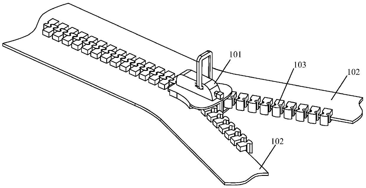
[0014] Such as figure 2 As shown, the present embodiment provides a zipper with a self-locking function, including a slider 101 , two chain straps 102 and several fastener elements 103 disposed on the chain straps 102 .

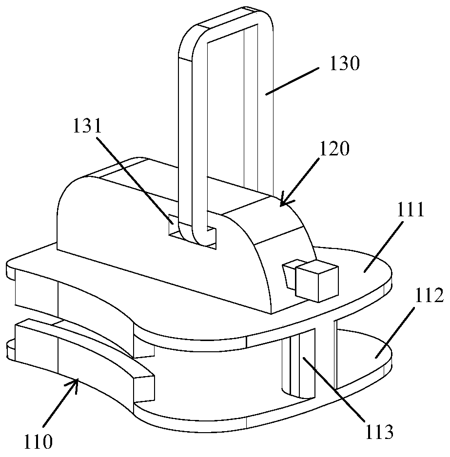
[0015] Such as image 3 As shown, the slider 101 includes a splint part 110 of plastic material for clamping the chain belt 102 therein, a locking part 120 on the splint part 110 and a plastic material on the locking part 120 The splint portion 110 includes an upper splint 111 and a lower splint 112 arranged in parallel and a column 113 connecting the upper splint 111 and the lower splint 112 , and the column 113 is located on the front side of the splint portion 110 . In the present invention, the so-called front side refers to the direction in which the slider 101 is pulled to engage the fastener elements 103 , and the so-c...


PUM


Abstract

The invention discloses a zipper with a self-locking function. The zipper comprises zipper heads, two zipper bands and multiple zipper teeth arranged on the zipper bands; the zipper heads comprise clamping board parts which are used for clamping the zipper bands inside and made of plastic, a locking part which is located on the clamping board parts and a pull ring which is located on the locking part and made of plastic, wherein the locking part comprises a vertical board part which is perpendicular to an upper clamping board and made of plastic, a square groove is formed in the vertical board part in the length direction, and a square hole is further formed in the portion, located on an extending line of the frontward side of the square groove, in the vertical board; a square rod made of plastic is inserted into the square hole and connected to a sliding block which is located in the square groove and made of plastic, and a magnet is fixed to the lower end surface of the sliding block. The self-locking zipper is simple in structure and convenient to operate, the locking part is arranged on the zipper, after the zipper teeth of two sides are meshed with each other, a pull head is clamped by the locking part and accordingly cannot slide, and thus the aim of locking is achieved.

Description

technical field [0001] The invention relates to a slide fastener with a self-locking function, which belongs to the technical field of slide fasteners. Background technique [0002] The zipper is a connecting piece that relies on the continuous arrangement of chain teeth to make items merge or separate. It is now widely used in clothing, bags, tents, etc. It is characterized by a buckle composed of two belts with a row of metal teeth or plastic teeth. A piece that joins the edge of an opening (such as the opening of a garment or bag) with a slide that pulls the two rows of teeth into an interlocking position to close the opening. Such as figure 1 As shown, the usual zipper is composed of chain element 1 and slider 2, wherein the chain element 1 is the key part, which directly determines the side pull strength of the zipper. Generally, the zipper has two chain tapes 3a, 3b, and each chain tape 3a, 3b has a row of fastener elements 1 respectively, and the two rows of fastene...

Claims


Application Information

Patent Timeline
Patent Type & Authority Patents(China)
IPC IPC(8): A44B19/30
CPCA44B19/305
Inventor 郑志华陈国红郑安安王飞董希文郑彬彬
Owner ZHEJIANG HENGWEI ZIPPER CO LTD
Why Eureka
Try Eureka