
Tied-arch floating bridge and tied-arch floating bridge erecting method

A technology of tied arch and pontoon bridge

Active Publication Date: 2017-11-24
PLA UNIV OF SCI & TECH
View PDF7 Cites 3 Cited by
  • Summary
  • Abstract
  • Description
  • Claims
  • Application Information

AI Technical Summary

Problems solved by technology

[0006] The purpose of the present invention is to provide a tie-arch pontoon bridge, which largely alleviates the technical problem in the prior art that the tie-arch pontoon bridge is inconvenient to disassemble during long-distance transportation.

Method used


Image

  • Tied-arch floating bridge and tied-arch floating bridge erecting method
  • Tied-arch floating bridge and tied-arch floating bridge erecting method
  • Tied-arch floating bridge and tied-arch floating bridge erecting method

Examples


Embodiment 1

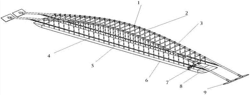
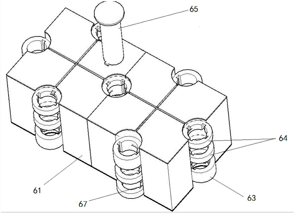
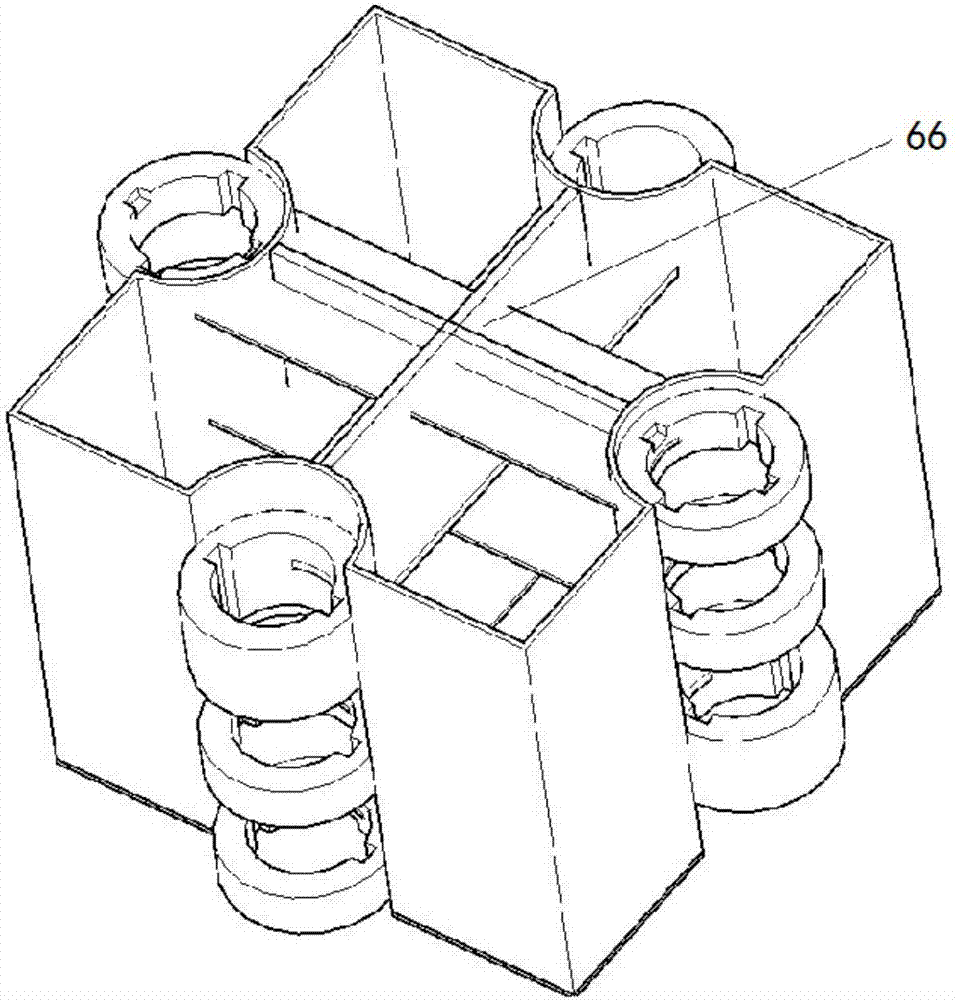
[0052] Such as Figure 1-Figure 9 As shown, a tie-arch floating bridge provided in this embodiment includes a floating body structure 6, a hoisting structure and an arch end support 9; the hoisting structure is arranged above the floating body structure 6, and can hoist the floating body structure 6; the hoisting structure , including at least two arch bodies 2, a plurality of tie rods 4, a plurality of vertical suspenders 5 and a plurality of cross braces 3; the two ends of each arch body 2 are respectively fixedly connected with the arch end supports 9; two adjacent arches The main bodies 2 are connected by a plurality of cross braces 3; the tops of the multiple vertical suspenders 5 are connected with the arch main body 2, and the bottoms are connected with the floating body structure 6; Each vertical suspension rod 5 on the top is connected, and the rod end of the tie rod 4 is fixedly connected with the corresponding arch main body 2.

[0053] This embodiment adopts the t...

Embodiment 2

[0070] On the basis of Embodiment 1, a method for erecting a tied arch pontoon bridge provided by this embodiment includes the following steps:

[0071] S001: Before air-dropping the floating structure 6 and the hoisting structure 6 as a whole or in sections to the predetermined water area, first splicing multiple floating tank units 61 on the level ground through the bolt 65 to form the floating body structure 6, and then placing the hoisting structure on the floating body structure 6 surface together for air transport;

[0072] S002: Lift the floating body structure 6 and the hoisting structure to the release site as a whole by helicopter: After the floating body structure 6 is dropped into the designated water area, first set up anchoring structures on both sides of the floating body structure 6, and then place anchor structures on the four corners of the floating body structure Pull out the mooring steel cable along the direction of 30° from the floating body on both sides...


PUM


Abstract

The invention provides a tied-arch floating bridge and a tied-arch floating bridge erecting method, and relates to the technical field of civil engineering. The tied-arch floating bridge comprises a floating body structure, a hoisting structure and arch abutment support seats, the hoisting structure is arranged above the floating body structure and capable of hoisting the floating body structure, the hoisting structure comprises at least two main arch bodies, a plurality of cross supports, a plurality of perpendicular hoisting rods and a plurality of tie rods, two ends of main arch bodies are fixedly connected with the arch abutment support seats respectively, every two main arch bodies are connected with each other through the transverse supports, top portions of the perpendicular hoisting rods are connected with the main arch bodies, bottom portions of the perpendicular hoisting rods are connected with the floating structure, rod bodies of the tie rods are connected with the perpendicular hoisting rods which are mounted on the corresponding main arch bodies, and rod ends of the tie rods are fixedly connected with the corresponding main arch bodies. The tied-arch floating bridge is simple in structure and convenient to disassemble and assemble.

Description

technical field [0001] The invention relates to the technical field of civil engineering, in particular to a tie-arch floating bridge and a method for erecting the tie-arch floating bridge. Background technique [0002] The existing pontoon bridge equipment and equipment in China have a single bridge structure. From the perspective of architectural aesthetics, the ornamental value is relatively poor. After adding the tie rod arch element, the ornamental value of the pontoon bridge is greatly increased, making tourist attractions or tourist resorts attractive to tourists. The ability can be greatly enhanced, and it is of great significance to promote the development of the service industry. [0003] At the same time, the self-weight of the existing domestic pontoon bridge equipment that can be quickly erected and withdrawn, and disassembled is relatively large (1100kg per longitudinal meter), and other bridge equipment with fixed bridge feet has a greater self-weight (1200kg ...

Claims


Application Information

Patent Timeline
Patent Type & Authority Applications(China)
IPC IPC(8): E01D15/14E01D21/00
CPCE01D15/14E01D21/00
Inventor 黄亚新林渊陈启飞张冬冬黄腾徐若航
Owner PLA UNIV OF SCI & TECH
Learn More