Sliding groove mechanism of rotary drilling rig follow-up frame

A technology of rotary drilling rig and follower frame, which is used in drilling equipment, earthwork drilling, wellbore/well components, etc. Service life, not easy to damage effect

Inactive Publication Date: 2017-11-24
广西同庆机械制造有限公司
View PDF6 Cites 0 Cited by
  • Summary
  • Abstract
  • Description
  • Claims
  • Application Information

AI Technical Summary

Problems solved by technology

[0005] The object of the present invention is to provide a chute mechanism for the follower frame of a rotary drilling rig, thereby overcoming the disadvantage that the chute of the existing follower frame is easily damaged due to the wear-resistant contact plate fixed by the countersunk screw, which leads to the failure of the follower frame

Method used


Image

  • Sliding groove mechanism of rotary drilling rig follow-up frame
  • Sliding groove mechanism of rotary drilling rig follow-up frame
  • Sliding groove mechanism of rotary drilling rig follow-up frame

Examples


Embodiment Construction

[0019] The specific embodiments of the present invention will be described in detail below in conjunction with the accompanying drawings, but it should be understood that the protection scope of the present invention is not limited by the specific embodiments.

[0020] Unless expressly stated otherwise, throughout the specification and claims, the term "comprise" or variations thereof such as "includes" or "includes" and the like will be understood to include the stated elements or constituents, and not Other elements or other components are not excluded.

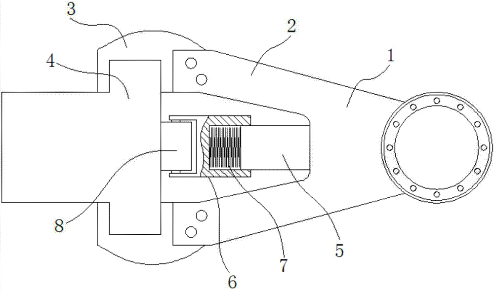
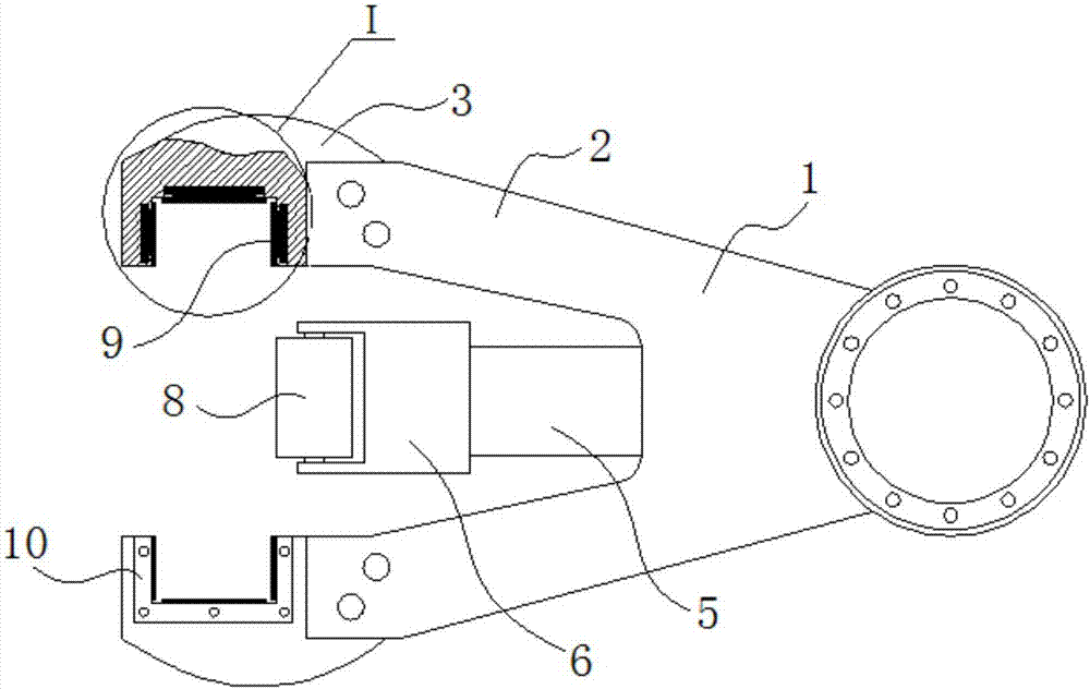
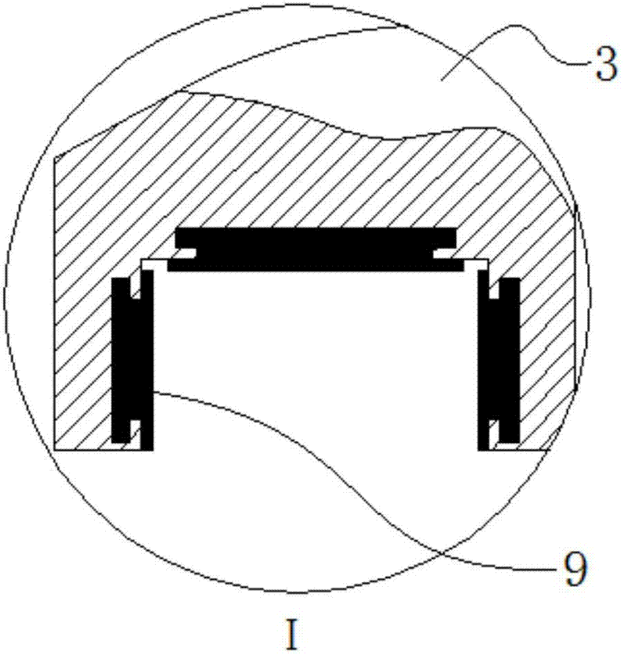
[0021] Figure 1 to Figure 3 A schematic structural diagram of a chute mechanism of a rotary drilling rig follower frame according to a preferred embodiment of the present invention is shown, the chute mechanism of the rotary drilling rig follower frame includes a chute 3, a wear-resistant contact plate 9, and a buffer sleeve 6 , buffer spring 7 and roller 8, refer to figure 1 with figure 2 Each of the two oppositely di...


PUM


Abstract

The invention discloses a sliding groove mechanism of a rotary drilling rig follow-up frame. The follow-up frame comprises sliding grooves, wear-resistant contact plates, a fixed column, a buffer sleeve, a buffer spring, and a roller; the sliding grooves with longitudinal distribution and U shape are arranged on each of two relatively distributed connecting arms of the follow-up frame; wear-resistant contact plates are arranged on three inner walls of the sliding grooves; the rear end of the fixed column is fixed on the follow-up frame, and the fixed column is located between the two connecting arms; an inner hole which can be arranged in the front end of the fixed column in a sleeved mode in a back and forth sliding mode is formed in the rear end of the buffer sleeve; the buffer spring is arranged inside the inner hole of the buffer sleeve, and the buffer spring is clamped between the bottom wall of the inner hole of the buffer sleeve and the front end of the fixed column; the roller is arranged on the front end of the buffer sleeve, and the roller is used for relying on a guide rail of a mast. The roller relies on the guide rail, the buffer spring is used for buffering and absorbing the vibration generated during the working process, the impact on the wear-resistant contact plate is reduced, and the service life of the follow-up frame is improved.

Description

technical field [0001] The invention relates to the field of rotary drilling rigs, in particular to a chute mechanism of a traveling frame of the rotary drilling rig. Background technique [0002] Rotary drilling rigs have high power, strong power and fast hole formation, and are widely used in engineering and building foundation construction. The rotary drilling rig is composed of a crawler chassis, a boarding part, a mast assembly, a drilling system and a hydraulic system. The crawler chassis is used for moving, and the boarding part and others are used for drilling operations. Drill rods in the drilling system of common rotary drilling rigs generally adopt a structure with a traveling frame to ensure the verticality of the borehole during the drilling, lifting and lowering of the rotary drilling rig. One end of the follower frame is connected to the drill pipe through the slewing support, and the other end is sleeved on both sides of the guide rail set on the mast throug...

Claims


Application Information

Patent Timeline
Patent Type & Authority Applications(China)
IPC IPC(8): E21B15/00E21B41/00
CPCE21B15/003E21B41/00
Inventor 宾奇贵宾奇富宾奇昌
Owner 广西同庆机械制造有限公司
Why Eureka
Try Eureka