Infrared thermal imaging air tightness tester

A technology of infrared thermal imaging and tester, which is applied in the direction of fluid tightness test, machine/structural component test, instrument, etc. It can solve the problems of ultrasonic method and achieve the effect of fast response speed and high temperature resolution

Pending Publication Date: 2017-11-24
THE INSPECTION & QUARANTINE TECH CENT ZHEJIANG ENTRY EXIT INSPECTION & QUARANTINE BUREAU +1
View PDF7 Cites 7 Cited by
  • Summary
  • Abstract
  • Description
  • Claims
  • Application Information

AI Technical Summary

Problems solved by technology

However, the first four methods cannot meet the user's technical requirements for locating the leak point. The ultrasonic method will have great difficulties in the practical application of the industrial field, and some users clearly require the use of thermal imaging detection technology to meet the user's needs and locate the leak point. Therefore, it is necessary to continue to develop a new thermal imaging leak detection test system to meet the needs and detection requirements of users and the market

Method used


Image

  • Infrared thermal imaging air tightness tester

Examples


Embodiment Construction

[0019] The present invention will be further described below in conjunction with the accompanying drawings and specific embodiments.

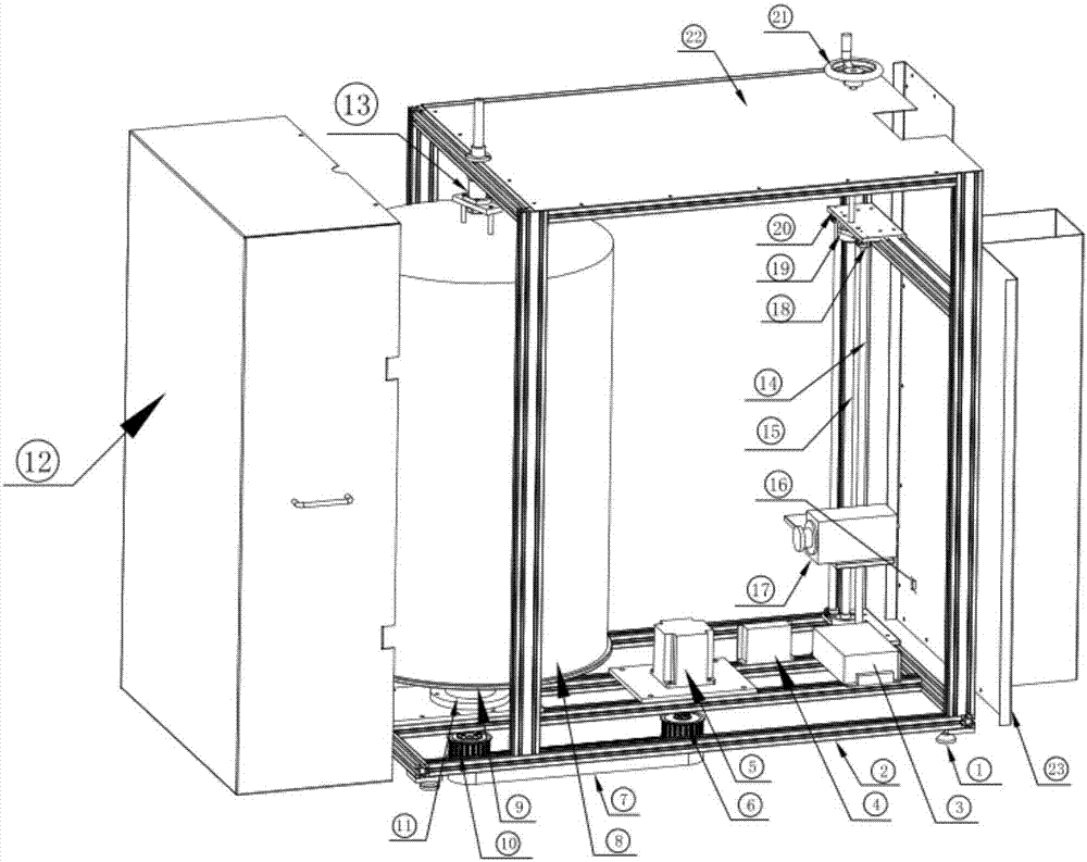
[0020] Such as figure 1 As shown, the infrared thermal imaging air tightness tester includes a test module, a control module, a thermal imaging module, a motion module, a data processing module and a tester frame. The tester frame includes a base plate, a support frame and an upper sealing plate; a foot is provided on the side of the base plate close to the ground, and one end of the foot is fixed on the base plate, and a rubber pad is provided at the other end, which can well buffer and reduce the The impact of possible external vibrations on the tester.

[0021] The test module includes a container to be tested, a turntable, a bearing seat, and a pressing rotating shaft. The container to be tested is cylindrical, and the upper end of the container to be tested is fixedly connected to the pressing shaft. The pressing shaft is fixed on the up...


PUM


Abstract

The invention discloses an infrared thermal imaging air tightness tester, comprising a test module, a control module, a thermal imaging module, a moving module, a data processing module and a tester frame; the tester frame comprises a bottom plate, a support frame and an upper seal plate; a foot pad is arranged on the side, close to the ground, of the bottom plate, one end of the foot pad is fixed on the bottom plate, and a rubber pad is arranged at the other end of the foot pad. The invention provides an infrared thermal imaging air tightness tester, which has high safety coefficient and can be monitored in real time.

Description

technical field [0001] The invention relates to the field of airtightness, more specifically, it relates to an infrared thermal imaging airtight tester. Background technique [0002] At present, the detection methods for airtight container leakage mainly include: water detection method, flow measurement method, direct pressure method, helium tracer method and ultrasonic measurement method. However, the first four methods cannot meet the user's technical requirements for locating the leak point. The ultrasonic method will have great difficulties in the practical application of the industrial field, and some users clearly require the use of thermal imaging detection technology to meet the user's needs and locate the leak point. Therefore, it is necessary to continue to develop a new thermal imaging leak detection test system to meet the needs and detection requirements of users and the market. Contents of the invention [0003] The invention overcomes the shortcomings of th...

Claims


Application Information

Patent Timeline
Patent Type & Authority Applications(China)
IPC IPC(8): G01M3/00
CPCG01M3/002
Inventor 万旺军白广宇余佳璟李丽霞王广宇
Owner THE INSPECTION & QUARANTINE TECH CENT ZHEJIANG ENTRY EXIT INSPECTION & QUARANTINE BUREAU
Why Eureka
Try Eureka