
A Shaft Vibration Monitoring Method of Asymmetric Combined Cycle Unit Based on Finite Element Theory

A combined cycle unit and shafting vibration technology, which is applied in special data processing applications, geometric CAD, design optimization/simulation, etc., can solve the difficulties in monitoring the shafting vibration of asymmetric combined cycle units, different dynamic stiffness, and stiffness asymmetry, etc. problem, to achieve the effect of convenient and fast shafting response analysis and comparison

Active Publication Date: 2020-04-28
XI AN JIAOTONG UNIV
View PDF6 Cites 0 Cited by
  • Summary
  • Abstract
  • Description
  • Claims
  • Application Information

AI Technical Summary

Problems solved by technology

Due to the asymmetric rigidity of the section of the generator, the static deflection of the rotor will be different when the rotor rotates to different angles, and the difference in deflection directly leads to the different dynamic stiffness at different angles, which leads to the phase vibration of the shaft system of the asymmetric combined cycle unit. Compared with the fully symmetrical shafting vibration, different characteristics appear, which brings great difficulties to the shafting vibration monitoring of asymmetric combined cycle units

Method used


Image

  • A Shaft Vibration Monitoring Method of Asymmetric Combined Cycle Unit Based on Finite Element Theory
  • A Shaft Vibration Monitoring Method of Asymmetric Combined Cycle Unit Based on Finite Element Theory
  • A Shaft Vibration Monitoring Method of Asymmetric Combined Cycle Unit Based on Finite Element Theory

Examples


Embodiment Construction

[0034] The present invention will be further described in detail below in conjunction with the accompanying drawings.

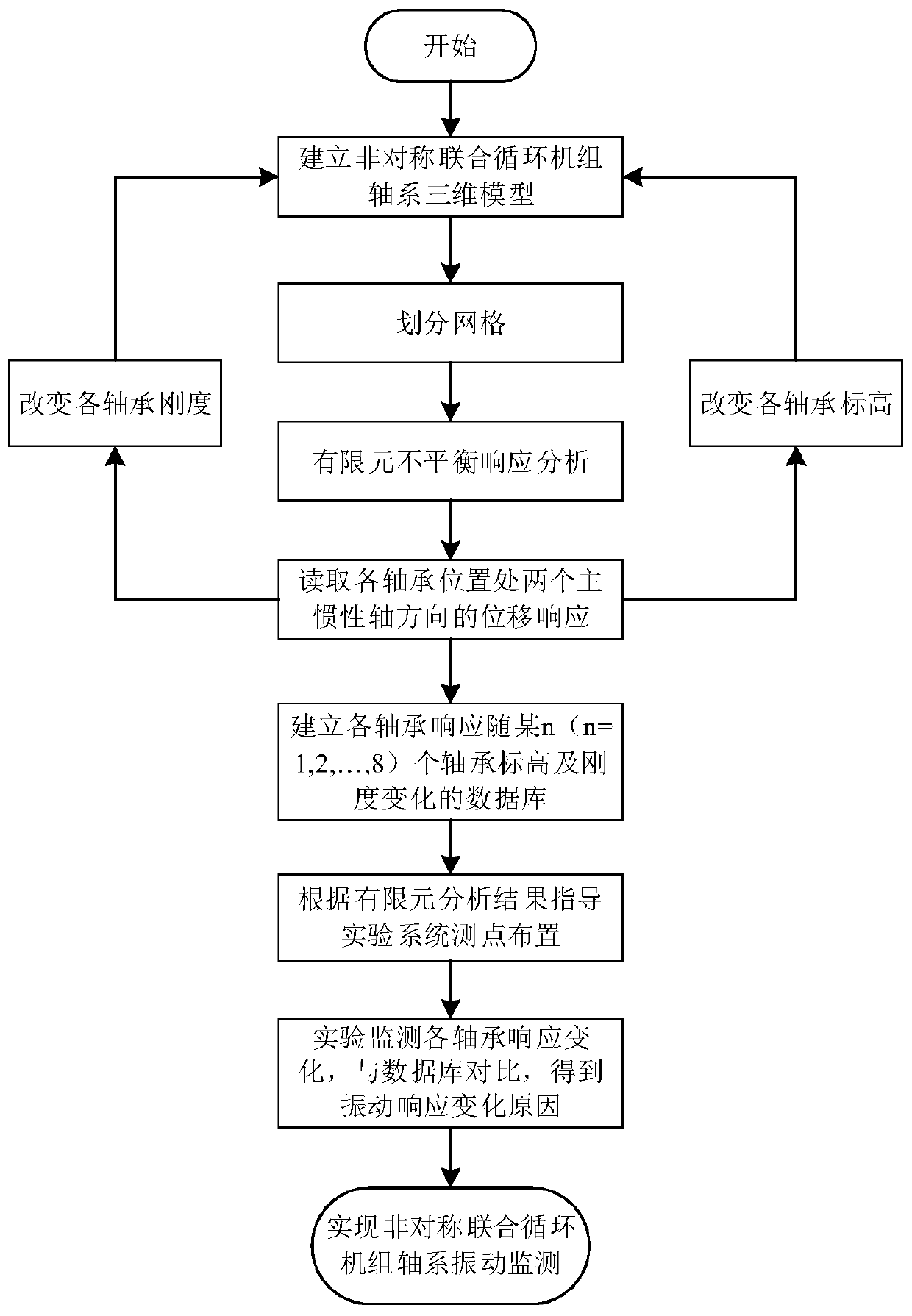
[0035] 1) see figure 1 , the present invention aims to establish a shafting vibration monitoring method for an asymmetric combined cycle unit based on finite element theory, which lays the foundation for the shafting vibration monitoring of an asymmetric combined cycle unit. Based on this purpose, an asymmetrical combined cycle unit based on finite element theory is designed. The overall flow chart of the vibration monitoring method for the shaft system of the combined cycle unit.

[0036] 2) Collect the geometric parameters of the shaft system of the asymmetric combined cycle unit, including the radius and length of each shaft section, the position and radius of each fillet. The three-dimensional model of the shaft system of the asymmetric combined cycle unit is obtained by three-dimensional modeling according to the geometric parameters. The shaft system ...


PUM


Abstract

The invention discloses an unsymmetrical combined cycle unit shafting vibration monitoring method based on the finite element theory. The unsymmetrical combined cycle unit shafting vibration monitoring method based on the finite element theory comprises the following steps: obtaining a finite element model through the three-dimensional modeling and the finite element mesh division of the unsymmetrical combined cycle unit shafting; obtaining a displacement response in the direction of two main inertia axes at each bearing position by applying boundary conditions to perform unbalanced response calculation; changing the elevation and stiffness of n (n = 1, 2,...,8) bearings at the same time successively in the change range of the common bearing elevation and stiffness to obtain the unbalance response at the 8 bearings; recording to obtain the response of each bearing with the changes of the bearing elevation and stiffness of a certain n bearings; and performing experimental determination on the unsymmetrical combined cycle unit shafting and arranging sensors for vibration monitoring. In the process of the experiment, the cause of the vibration response change can be obtained through detecting the vibration changing law of each bearing and finding the corresponding working conditions in the database, so that the vibration monitoring of the unsymmetrical combined cycle unit shafting is realized.

Description

Technical field: [0001] The invention relates to a vibration monitoring method for shafting of an asymmetric combined cycle unit based on finite element theory. Background technique: [0002] Since the end of the 20th century, power generation technology has become increasingly mature, major changes have taken place in the structure of energy resources around the world, and people's requirements for environmental protection have also increased. The obvious advantages such as short length, small footprint, and minimal environmental pollution have become more and more important in the power system, and gradually replacing coal-fired heating units has become the main development trend. [0003] In the construction process of major thermoelectric centers, asymmetric air-cooled generator rotors are gradually applied to the shafting of combined cycle units. The section stiffness of the generator rotor adopts an asymmetric form, the rotor body is cylindrical, and the surface is mi...

Claims


Application Information

Patent Timeline
Patent Type & Authority Patents(China)
IPC IPC(8): G06F30/23G06F30/17
CPCG06F30/17G06F30/23
Inventor 张荻杜秋晚郑召利谢永慧
Owner XI AN JIAOTONG UNIV
Learn More