
Square wave chamfering circuit and drive method thereof and display panel

A technology of cutting corners and circuits, which is applied to static indicators, instruments, etc., can solve problems such as flickering and afterimages on the display panel, gate drive circuits that cannot complete the step-down and corner cutting of the output terminal, and affect the quality of the picture displayed on the display panel.

Active Publication Date: 2017-11-24
BOE TECH GRP CO LTD +1
View PDF5 Cites 7 Cited by
  • Summary
  • Abstract
  • Description
  • Claims
  • Application Information

AI Technical Summary

Problems solved by technology

However, the gate drive circuit cannot complete the step-down and chamfering function of the output end, which will lead to a large voltage drop at the output end, which will cause flickering and afterimages on the display panel, and seriously affect the quality of the picture displayed on the display panel.

Method used


Image

  • Square wave chamfering circuit and drive method thereof and display panel
  • Square wave chamfering circuit and drive method thereof and display panel
  • Square wave chamfering circuit and drive method thereof and display panel

Examples


Embodiment Construction

[0044]In order to make the purpose, technical solution and advantages of the present invention clearer, the specific implementations of the square-wave chamfering circuit provided by the embodiment of the present invention, its driving method and the display panel will be described in detail below with reference to the accompanying drawings. It should be understood that the preferred embodiments described below are only used to illustrate and explain the present invention, not to limit the present invention. And in the case of no conflict, the embodiments in the present application and the features in the embodiments can be combined with each other.

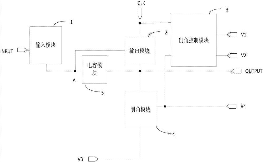
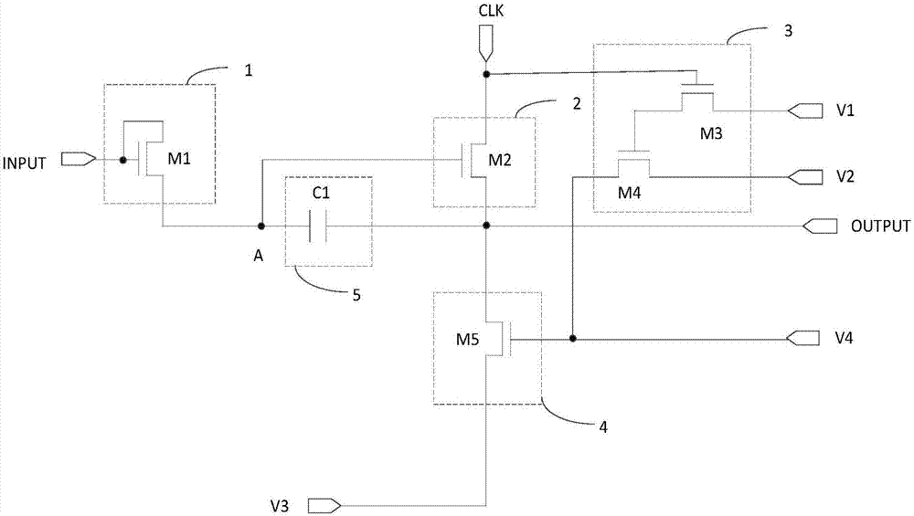
[0045] The embodiment of the present invention provides a square wave clipping circuit, such as figure 1 As shown, it includes: input module 1, output module 2, chamfering control module 3, chamfering module 4 and capacitor module 5; wherein,

[0046] The input module 1 is respectively connected to the input signal terminal INPU...


PUM


Abstract

The invention discloses a square wave chamfering circuit and a drive method thereof and a display panel. The circuit comprises an input module, an output module , a chamfering control module, a chamfering module and a capacitor module, square wave signals input into the signal input end can form signals in chamfering wave shapes when output to the signal output end through the coordination of the five modules, thus the output signals are changed from rectangular sudden change to slope slow descent, accordingly the adverse influences brought by electrical level sudden change when the square wave signals are changed from a high electrical level to a low electrical level can be reduced, and in this way, when the square wave chamfering circuit is applied to the display panel, the quality of displayed pictures can be improved.

Description

technical field [0001] The invention relates to the field of display technology, in particular to a square-wave angle-cutting circuit, a driving method thereof, and a display panel. Background technique [0002] Display panels in the prior art generally display in a progressive scanning manner, that is, within a frame time, when pixels in the Nth row are turned on, other rows are turned off. When a row is turned on, the data signal charges all the pixels in the row. After the charging is completed, the next row is turned on and the row is turned off, and the row maintains the data signal until the scanning of one frame is completed. [0003] With the development of display technology, display panels use gate drive circuits instead of gate drive chips to complete the progressive scan function, that is, by combining switching transistors and capacitors to form a gate drive circuit to complete the progressive scan function, reducing the The production cost of the display panel...

Claims


Application Information

Patent Timeline
IPC IPC(8): G09G3/36G09G3/3208
CPCG09G3/3208G09G3/36
Inventor 王会明梁魁张伟陈沫刘冬杨秀琴
Owner BOE TECH GRP CO LTD
Learn More