Power supply circuit

A technology of power supply circuit and voltage divider circuit, applied in the direction of high-efficiency power electronic conversion, electrical components, adjusting electrical variables, etc., can solve the problems of LDO power supply damage, increased heat generation, large output ripple noise, etc., and achieve low ripple noise. , Low power consumption voltage, the effect of solving the output voltage ripple noise

Pending Publication Date: 2020-05-29
SUZHOU HUAXING YUANCHUANG TECH CO LTD
View PDF0 Cites 3 Cited by
  • Summary
  • Abstract
  • Description
  • Claims
  • Application Information

AI Technical Summary

Problems solved by technology

[0003] In the existing power supply design, the DC / DC BUCK power supply solution is usually adopted, but because of its own high-frequency switching characteristics, the output ripple noise of the DC / DC BUCK power supply is relatively large, and it is difficult to meet the requirements of low ripple noise.
If the LDO power supply is used, although the output ripple noise can be controlled ideally, the input voltage of the LDO power supply must have a certain voltage difference from its output voltage to ensure that it has a normal voltage output. If the voltage difference increases, Then the power consumption of the LDO power supply will increase, resulting in an increase in heat generation. When the heat generation exceeds the maximum junction temperature of the LDO power supply, it will cause damage to the LDO power supply.
[0004] It can be seen that whether the DC / DC BUCK power supply scheme is adopted or the LDO power supply is sampled, there are defects, which cannot meet the output requirements of the liquid crystal module for the power supply during the detection process.

Method used


Image

  • Power supply circuit
  • Power supply circuit
  • Power supply circuit

Examples


Embodiment Construction

[0029] The present invention will be further described in detail below in conjunction with the accompanying drawings and embodiments. It should be understood that the specific embodiments described here are only used to explain the present invention, but not to limit the present invention. In addition, it should be noted that, for the convenience of description, only some structures related to the present invention are shown in the drawings but not all structures.

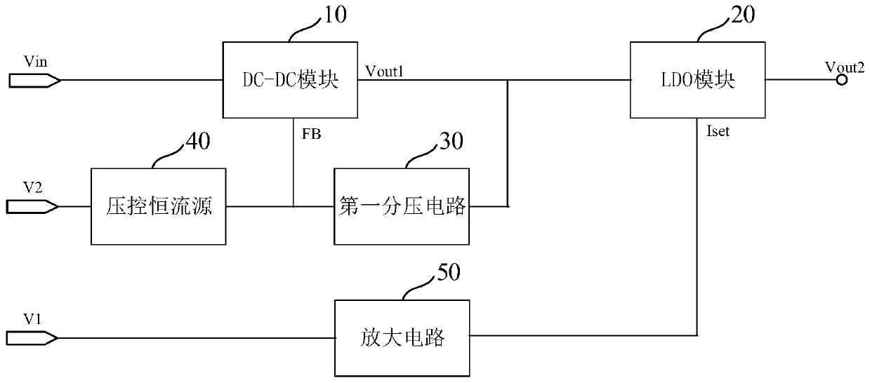
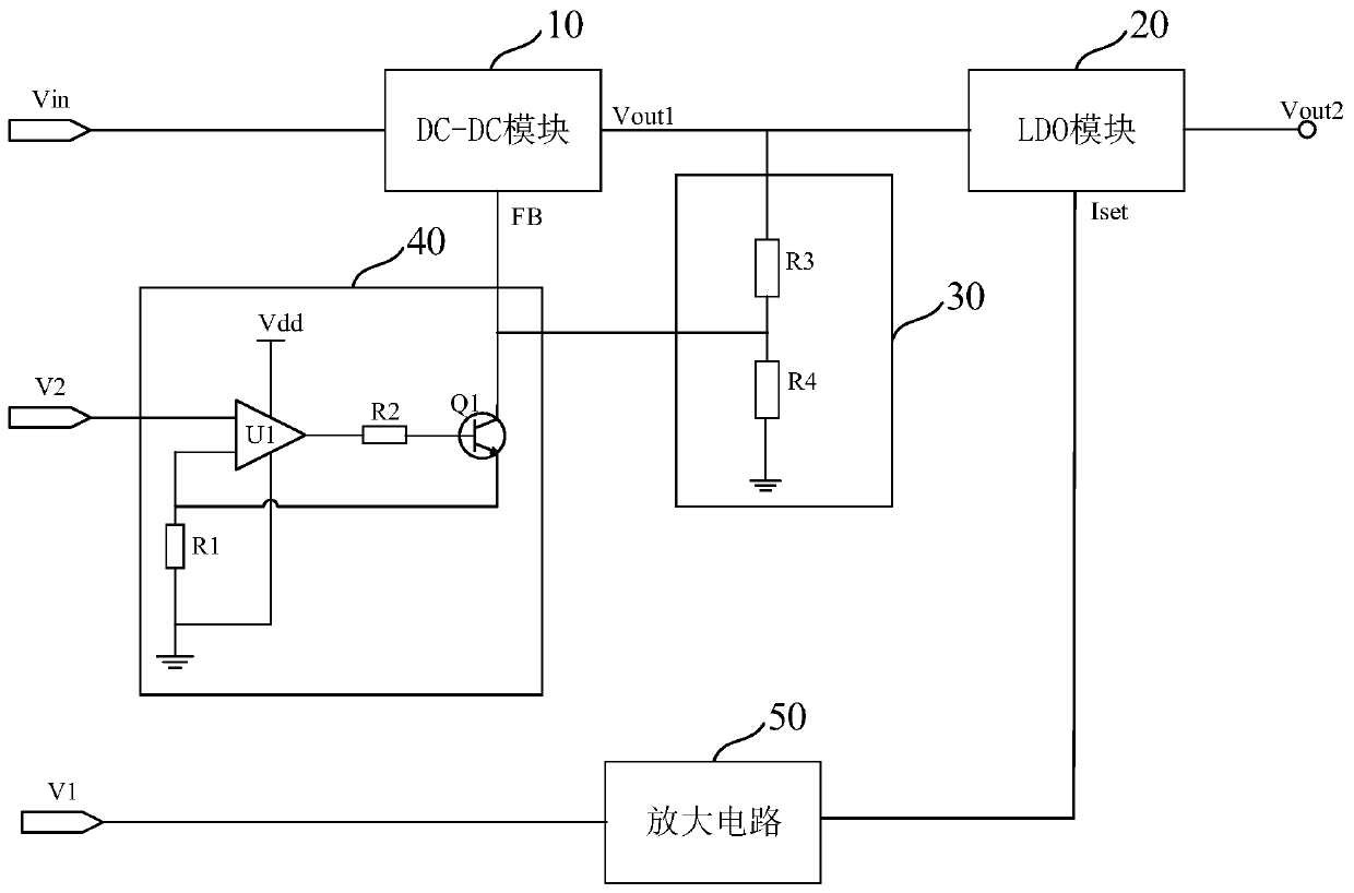
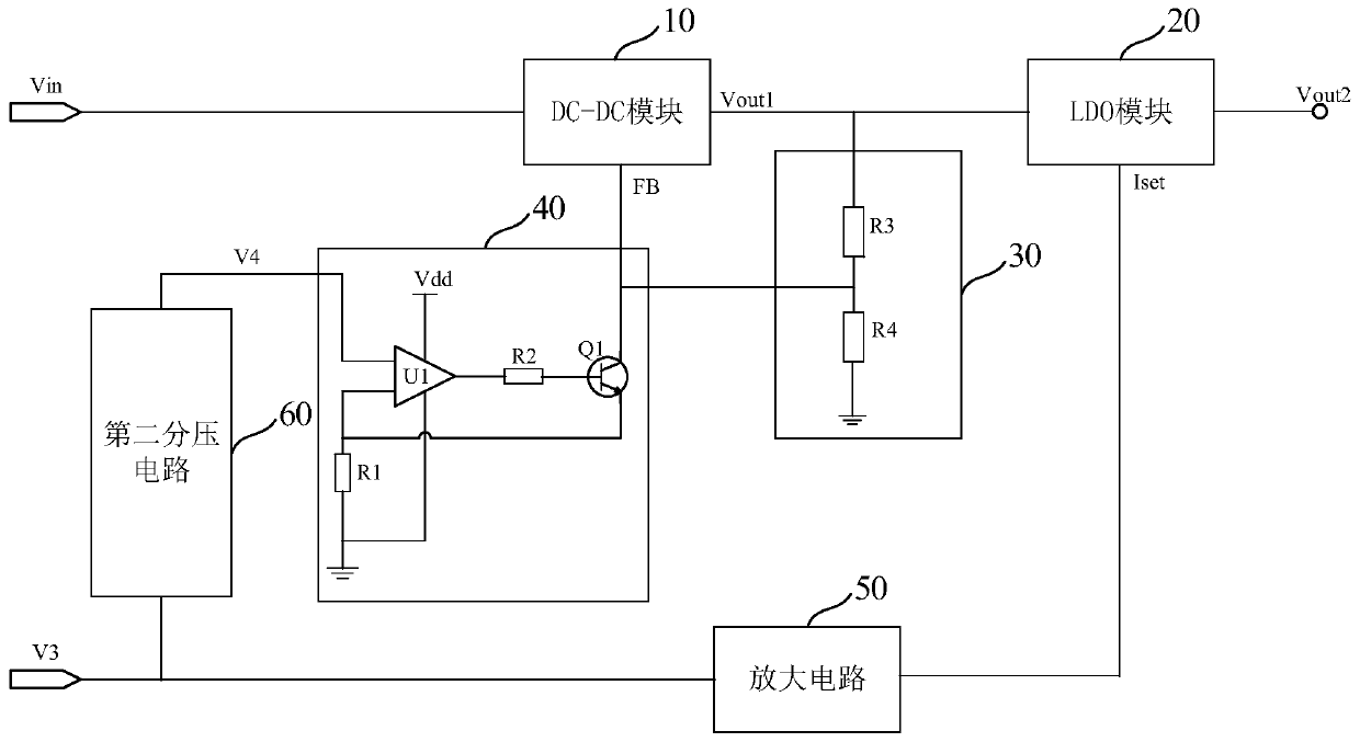
[0030] figure 1 It is a schematic structural diagram of a power supply circuit provided by an embodiment of the present invention. This embodiment is applicable to provide power for liquid crystal module detection equipment, so as to control the output ripple of the power supply to a minimum and reduce the power consumption of the power supply. Such as figure 1 As shown, the power supply circuit includes: a DC-DC module 10, an LDO module 20, a first voltage divider circuit 30, a voltage-controlled constant curren...


PUM


Abstract

The invention discloses a power supply circuit. The power supply circuit comprises a DC-DC module, an LDO module, a first voltage division circuit, a voltage-controlled constant current source and anamplification circuit. An output end of the DC-DC module is connected with an input end of the LDO module, the input end of the first voltage division circuit is connected with the output end of the DC-DC module, the output end of the first voltage division circuit is connected with a feedback input end of the DC-DC module, and the first voltage division circuit divides a voltage of the input endand outputs the divided voltage from the output end; a first set voltage is input into the input end of the amplification circuit, and the output end of the amplification circuit is connected with anoutput voltage control end of the LDO module; and a first end of the voltage-controlled constant current source inputs a second set voltage, a second end of the voltage-controlled constant current source is connected with the output end of the first voltage division circuit, and the voltage-controlled constant current source controls the current of the second end according to the voltage of the first end. By adjusting input signals of the voltage-controlled constant current source and the amplification circuit, input and output of the LDO module are controlled to have a stable voltage difference, and voltage signals with low power consumption and a low ripple noise are output.

Description

technical field [0001] The embodiment of the present invention relates to a display module testing technology, in particular to a power supply circuit. Background technique [0002] At present, the power supply for the display module (such as the liquid crystal module) is required to have output characteristics such as low ripple noise, and the output voltage can be adjusted from 0V to meet the detection requirements of the liquid crystal module. [0003] In the existing power supply design, the DC / DC BUCK power supply scheme is usually adopted, but because of its own high-frequency switching characteristics, the output ripple noise of the DC / DC BUCK power supply is relatively large, and it is difficult to meet the requirements of low ripple noise . If the LDO power supply is used, although the output ripple noise can be controlled ideally, the input voltage of the LDO power supply must have a certain voltage difference from its output voltage to ensure that it has a normal...

Claims


Application Information

Patent Timeline
Patent Type & Authority Applications(China)
IPC IPC(8): H02M3/156H02M3/335H02M1/14
CPCH02M1/14H02M3/156H02M3/33507H02M1/0048Y02B70/10
Inventor 樊定
Owner SUZHOU HUAXING YUANCHUANG TECH CO LTD
Why Eureka
Try Eureka