
Adaptive power supply voltage regulation circuit

A technology of voltage regulation circuit and self-adaptive power supply, which is applied in the direction of regulating electrical variables, control/regulating systems, electrical components, etc., and can solve the problems of inability to cause inverter to reverse, unstable voltage, abnormal device function, etc.

Active Publication Date: 2022-04-19
SPREADTRUM COMM (SHANGHAI) CO LTD
View PDF0 Cites 0 Cited by
  • Summary
  • Abstract
  • Description
  • Claims
  • Application Information

AI Technical Summary

Problems solved by technology

[0004] However, for the clock circuit powered by the above-mentioned PMU combined with other power supply voltages, when switching between the two voltage domains (also called power domains), due to the influence of the process angle, the voltage actually applied to the inverter by the PMU There is a problem of instability, and the power supply voltage that is too high or too low will affect the normal operation of the device in the clock circuit, such as causing the inverter to fail to open normally, or causing the device to function abnormally
[0005] Specifically, since the transistor used in the inverter of the clock circuit is usually a Metal Oxide Semiconductor Field Effect Transistor (MOSFET) using Low Voltage Technology (LVT for short), the process , voltage and temperature (process, voltage, temperature, referred to as PVT) process angle, when directly using the PMU to supply power to the inverter, the voltage applied to the inverter is likely to be too high, affecting LVT performance (reliability)
[0006] In addition, when switching from the PMU to other power supply voltages, if the voltage applied by the PMU to the inverter is too low, it will cause the inverter to flip normally even if the clock circuit input is at a high level when switching to other power supply voltages.

Method used


Image

  • Adaptive power supply voltage regulation circuit
  • Adaptive power supply voltage regulation circuit

Examples


Embodiment Construction

[0026] As mentioned in the background art, in order to reduce product power consumption and area, the existing clock circuit removes the LDO and directly uses the power supply voltage provided by the PMU. However, when crossing the power domain (that is, crossing the voltage domain), due to the influence of the process angle, it is easy to cause the device to fail to turn on normally, resulting in abnormal function.

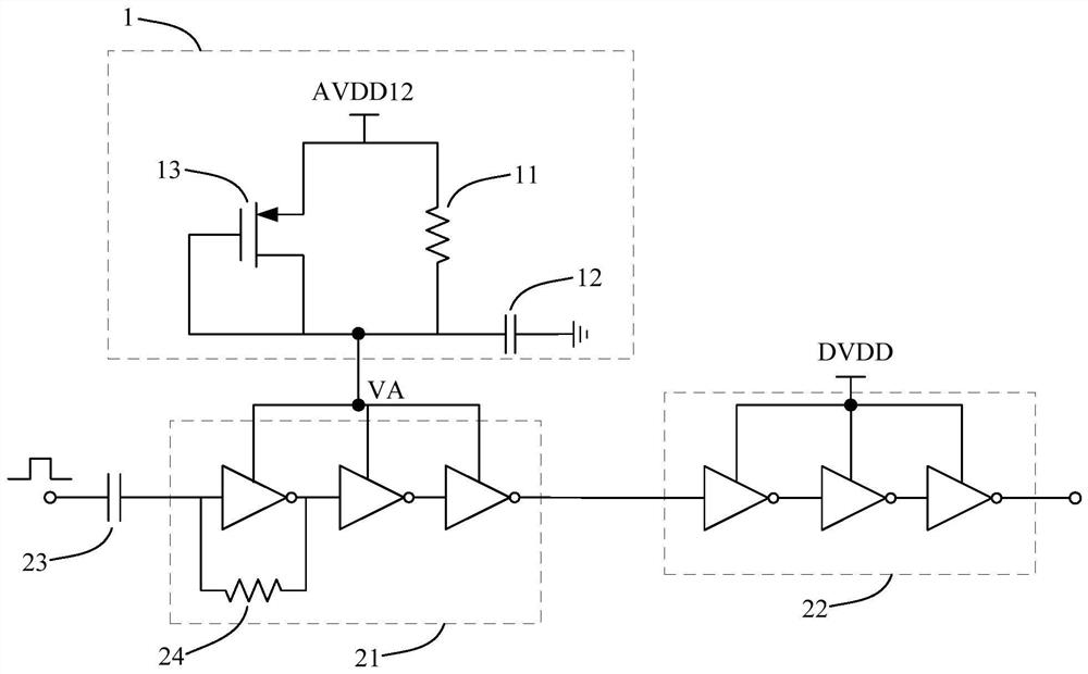
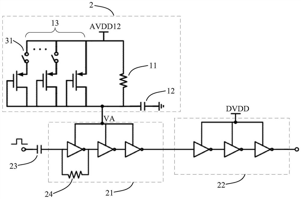
[0027] In order to solve the above technical problems, an embodiment of the present invention provides an adaptive power supply voltage regulation circuit, including: an RC filter, the RC filter includes a resistor and a capacitor connected in series, and the first end of the resistor is coupled to the power supply voltage end, the second end of the resistor is an output end, and the power supply voltage end is used to provide a power supply voltage; a shunt module, the shunt module is connected in parallel with the resistor to provide a connection between the pow...


PUM


Abstract

An adaptive power supply voltage regulation circuit, comprising: an RC filter, the RC filter includes a resistor and a capacitor connected in series, the first end of the resistor is coupled to the power supply voltage end, and the second end of the resistor is an output end, the power supply voltage end is used to provide a power supply voltage; a shunt module, the shunt module is connected in parallel with the resistor to provide a shunt branch between the power supply voltage end and the output end, and the shunt The number of branches is adjusted according to the voltage difference between the two ends of the resistor, so as to adjust the output voltage of the output terminal. The solution of the invention can realize self-adaptive adjustment of the power supply voltage to stabilize the output voltage within a suitable range, and is especially beneficial to ensure the normal operation of electric devices whose power supply voltage needs to be switched between multiple voltage domains.

Description

technical field [0001] The invention relates to the technical field of chip design, in particular to an adaptive power supply voltage regulation circuit. Background technique [0002] Multiple power supplies are usually set in the existing clock circuit, therefore, voltage domain conversion is involved in the operation of the clock circuit. In order to ensure the stability of the power supply to the inverter in the clock circuit before and after the voltage domain conversion, the prior art usually uses a low dropout linear regulator (Low Dropout Regulator, LDO for short) to provide the power supply for the inverter, but the additional LDO Will increase chip area and power consumption. [0003] In order to save chip area and power consumption, an existing clock circuit removes the LDO, and directly uses the power supply voltage provided by the power management unit (Power Management Unit, PMU for short) as the power supply voltage of the inverter. Specifically, the power su...

Claims


Application Information

Patent Timeline
Patent Type & Authority Patents(China)
IPC IPC(8): H02M3/04H02M3/156H02M3/158
CPCH02M3/04H02M3/156H02M3/1584H02M1/008
Inventor 汪然金玮罗大猷万中原郭义龙
Owner SPREADTRUM COMM (SHANGHAI) CO LTD
Learn More