Switching power supply circuit

A technology of switching power supply circuits and switches, which is applied in the field of switching power supply circuits and switching power supplies, can solve problems such as efficiency loss and achieve the effect of reducing size

Pending Publication Date: 2018-07-10
六安市华海电子器材科技有限公司
View PDF0 Cites 0 Cited by
  • Summary
  • Abstract
  • Description
  • Claims
  • Application Information

AI Technical Summary

Problems solved by technology

Any attempt to adjust VPA will result in a loss of efficiency equivalent to adding a linear regulator between C2 and VPA, and this circuit requires T1 and T2 to be non-overlapping clock signals to avoid a large loss in efficiency

Method used


Image

  • Switching power supply circuit
  • Switching power supply circuit
  • Switching power supply circuit

Examples


Embodiment Construction

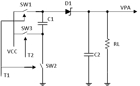
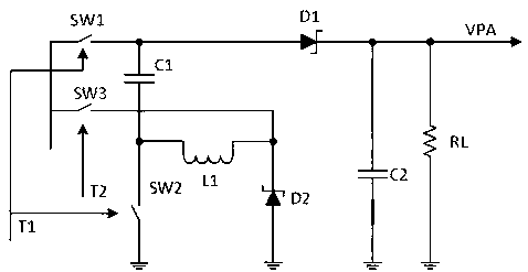
[0022] refer to figure 1 —— image 3 , the switching power supply includes a power supply VCC, a switch SW1, one end of which is connected to VCC, and the other end is connected to one end of capacitor C1, the other end of C1 is connected to one end of switch SW2, the other end of switch SW2 is grounded, and one end of switch SW2 is connected to the inductor L1 One end, the other end of the inductor L1 is connected to one end of the diode D2, the other end of the diode D2 is grounded, one end of the diode D2 is also connected to one end of the switch SW3, the other end of the switch SW3 is connected to VCC, the connection point of the switch SW1 and the capacitor C1 is connected to the diode D1 One end of the diode D2 is connected to one end of the capacitor C2, the other end of the capacitor C2 is grounded, the load electronics RL is connected in parallel with the capacitor C2, the connection point of the diode D1 and the capacitor C2 is the output node of the switching power...


PUM


Abstract

The invention relates to a switching power supply circuit which comprises a voltage multiplying circuit, an inductor connected to a power supply, a memory capacitor, at least one second switch and a control switch, wherein the voltage multiplying circuit comprises a power output line and at least one first switch. The control circuit controls the first and second switches and a first time period,within the first time period, both the first and second switches are closed, and the length of the first time period is adjusted to adjust an output voltage of the switching power supply circuit. Theswitching power supply circuit serves as a mini high-efficiency boosting adjuster, the capacitor provides a primary boost effect, and the inductor is used for further adjustment and boosting. Non-overlapped clock signals are not needed, and compared with a boost circuit, the size of the inductor can be reduced, the volume is reduced and the circuit structure is compact.

Description

technical field [0001] The invention relates to the technical field of switching power supplies, in particular to the field of switching power supply circuits. Background technique [0002] Voltage supplies are well known and include a "step-up" circuit for producing a higher voltage than the mains and a "step-down" circuit for producing a lower voltage. [0003] attached figure 1 A simple voltage doubler in the prior art is shown. In this switching power supply circuit, the connection point of switch SW1 and capacitor C1 is marked as node 1, the node of capacitor C1 and switch SW2 is marked as node 2, one end of capacitor C1 is connected to one end of switch SW1 through node 1, and the other end of switch SW1 is connected to VCC , that is, capacitor C1 is connected to VCC through switch SW1. One end of Schottky diode D1 is also coupled to node 1, and one end of capacitor C2 is coupled to the other end of D1. The connection point between D1 and capacitor C2 is the output ...

Claims


Application Information

Patent Timeline
IPC IPC(8): H02M3/07
CPCH02M3/07
Inventor 司红梅
Owner 六安市华海电子器材科技有限公司
Why Eureka
Try Eureka