Parallel structural hybrid excitation synchronous generator without electrical excitation rotor

A technology of electric excitation and generator, applied in the direction of magnetic circuit shape/style/structure, magnetic circuit rotating parts, electrical components, etc., can solve the problems of multiple electric excitation magnetomotive force, reduce electric excitation efficiency, consumption, etc., to achieve High electric excitation efficiency, increased reliability and environmental adaptability, less magnetomotive force

Inactive Publication Date: 2012-11-21
NORTH CHINA ELECTRIC POWER UNIV (BAODING)
View PDF3 Cites 0 Cited by
  • Summary
  • Abstract
  • Description
  • Claims
  • Application Information

AI Technical Summary

Problems solved by technology

However, the electric excitation part adopts the claw pole motor structure. In addition to the working air gap, there are two additional air gaps on the electric excitation magnetic circuit, which consumes more electric excitation magnetomotive force and reduces the electric excitation efficiency.

Method used


Image

  • Parallel structural hybrid excitation synchronous generator without electrical excitation rotor
  • Parallel structural hybrid excitation synchronous generator without electrical excitation rotor
  • Parallel structural hybrid excitation synchronous generator without electrical excitation rotor

Examples


Embodiment Construction

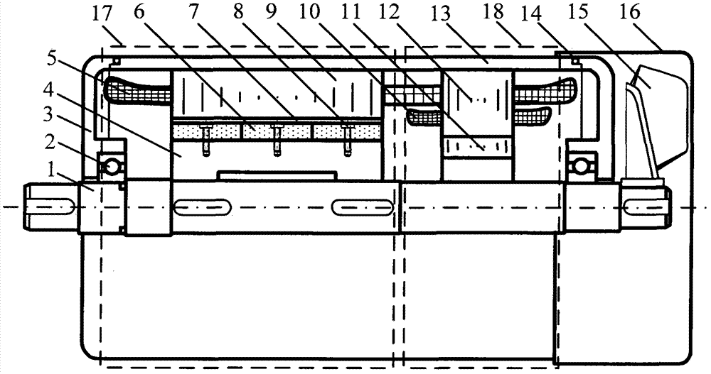
[0028] Depend on figure 1 It can be seen that the parallel structure hybrid excitation synchronous generator without electric excitation rotor of the present invention is composed of the permanent magnet synchronous generator part 17 on the left and the electric excitation part 18 on the right, which are coaxially arranged in the same casing 13 . The stator core 9 of the permanent magnet part and the stator core 12 of the electric excitation part are both made of laminated silicon steel sheets, and have the same number of slots. This embodiment has 36 slots. The stator slots of the electric excitation part are deeper than those of the permanent magnet part. Some stators share a set of three-phase armature windings 5 ​​. Another set of symmetrical three-phase electric excitation winding 10 is embedded in the electric excitation stator core 12 .

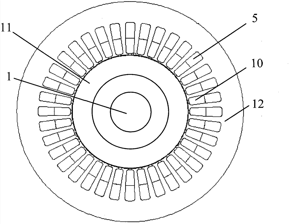
[0029] Such as figure 2 As shown, a magnetic conduction ring 11 is added to the inner circle of the stator 12 of the electric exci...


PUM


Abstract

The invention relates to a parallel structural hybrid excitation synchronous generator without an electrical excitation rotor, comprising a permanent magnet motor (17) and an electrical excitation part (18) which are coaxially arranged in a case (13) in parallel, wherein the two parts of magnetic circuits are independent; an armature winding (5) is respectively arranged in stator cores of the twoparts, and another three-phase or multiphase excitation winding (10) is arranged in the electrical excitation stator core (12); a magnetic conductive ring (11) is arranged at the inner circle of the electrical excitation stator core (12) to provide a pathway for an electrical excitation magnetic field and an armature magnetic field; and the size and the phase of current in the excitation winding (10) are changed through a frequency converter to adjust the size and the phase of the electrical excitation electromotive force in the armature winding (5), thereby reaching the purpose of changing the output voltage size. Because the electrical excitation part has no air gap, the required magnetic motive force of the electrical excitation is little and the adjusting efficiency of the magnetic field is high. Irreversible demagnetization to a permanent magnet cannot be caused by the electrical excitation magnetic motive force; and the reliability of the motor is high by utilizing brushless alternating current excitation.

Description

technical field [0001] The invention relates to a hybrid excitation synchronous motor, in particular to a parallel structure hybrid excitation synchronous generator with no electric excitation rotor. Background technique [0002] Compared with the traditional electric excitation synchronous motor, the permanent magnet synchronous motor has the advantages of high reliability, high efficiency and small size. However, since the rotor of the permanent magnet motor is excited by permanent magnet steel, the air gap magnetic field is not easy to adjust. When operating as a generator, when the temperature rises, the permanent magnet steel will produce reversible demagnetization, which will reduce the output voltage of the generator. In addition, when When the generator load changes, especially when the inductive load increases, the output voltage decreases further. Generally, the voltage change rate of the permanent magnet generator is about ±10%, which has an adverse effect on the...

Claims


Application Information

Patent Timeline
Patent Type & Authority Patents(China)
IPC IPC(8): H02K16/04H02K1/27H02K1/14
Inventor 刘明基宋中阳罗应立蔡中勤
Owner NORTH CHINA ELECTRIC POWER UNIV (BAODING)
Why Eureka
Try Eureka