An ion emission device and method for increasing ion implantation beam current

A technology of ion implantation and ion emission, which is applied to discharge tubes, electrical components, circuits, etc., can solve the problems of limited plasma quantity, too small ion quantity, and low ion quantity, so as to reduce the scanning time, increase the ion quantity, and improve the The effect of uniformity

Active Publication Date: 2019-08-20
SHANGHAI INTEGRATED CIRCUIT RES & DEV CENT
View PDF7 Cites 0 Cited by
  • Summary
  • Abstract
  • Description
  • Claims
  • Application Information

AI Technical Summary

Problems solved by technology

However, the number of plasma ionized by the ion source is limited each time, and more ions are required for each scan in the wide-beam scan. If more ions cannot be implanted at one time, the amount of ions will be less during the ion implantation process. Implantation of non-uniform defects on the wafer to be processed
Therefore, in the wide-beam scanning process using existing devices, the number of ions in the ion implantation beam is too small to become a serious defect in the ion implantation process

Method used


Image

  • An ion emission device and method for increasing ion implantation beam current
  • An ion emission device and method for increasing ion implantation beam current
  • An ion emission device and method for increasing ion implantation beam current

Examples


Embodiment 1

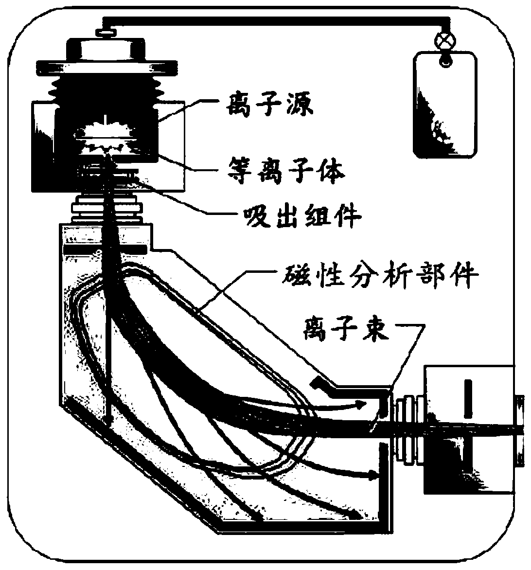
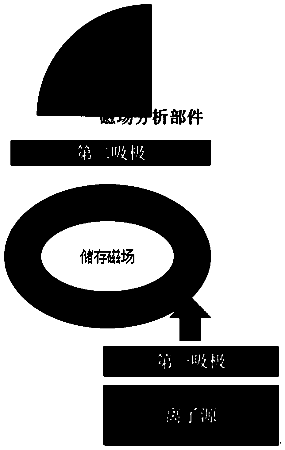
[0037] Such as figure 1 As shown, an ion emission device for increasing ion implantation beam current, which includes an ion source, a first suction pole, a storage magnetic field, a second suction pole and a magnetic analysis component, wherein the first suction pole is arranged on the ion source In the exit direction, the first suction pole is an electric field, and the voltage generating the electric field is a DC voltage. The storage magnetic field is deflected by a certain angle with the outlet of the first suction pole, and the angle makes the ions passing through the first suction pole enter the storage magnetic field and make a circular motion, and the storage magnetic field is a circular magnetic field set by the coil. The second suction pole is arranged at a position between the annular storage magnetic field and the magnetic analysis part, and the magnetic analysis part is used for detecting and separating ions in the storage magnetic field.

[0038] The ions ioniz...

Embodiment 2

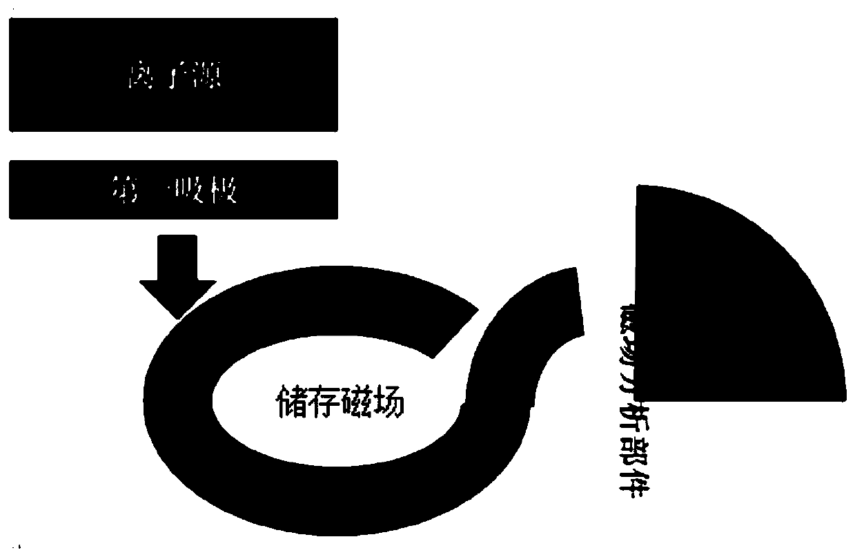
[0040] Such as figure 2As shown, an ion emission device for increasing ion implantation beam current, which includes an ion source, a first suction pole, a storage magnetic field, a deflection magnetic field and a magnetic analysis component, wherein the first suction pole is arranged in the exit direction of the ion source , the first absorber is an electric field, and the voltage generating the electric field is a DC voltage. The storage magnetic field is deflected at a certain angle from the outlet of the first suction pole, and this angle makes the ions passing through the first suction pole enter the storage magnetic field to make a circular motion. The storage magnetic field is a circular magnetic field set by a coil, and a gap that can be opened is set on the storage magnetic field . The deflection magnetic field connects the gap position of the storage magnetic field and the entrance of the magnetic analysis part, and the magnetic analysis part is used for detecting ...

Embodiment 3

[0043] Such as figure 1 As shown, an ion emission device for increasing ion implantation beam current, which includes an ion source, a first suction pole, a storage magnetic field and a magnetic analysis component, wherein the first suction pole is arranged in the direction of the exit of the ion source, and the first The attractor is an electric field, and the voltage generating the electric field is a DC voltage. The storage magnetic field is deflected at a certain angle from the outlet of the first suction pole, and this angle makes the ions passing through the first suction pole enter the storage magnetic field and make a circular motion. There is a gap that can be opened in the storage magnetic field, and the magnetic analysis component is arranged on the tangent of the gap. In the direction, the magnetic analysis component is used to detect and separate ions in the storage magnetic field.

[0044] The ions ionized by the ion source are drawn out through the first suctio...


PUM


Abstract

The invention discloses an ion emission method for increasing ion implantation beam. The device comprises an ion source, a first drain, a storage magnetic field and a magnetic analysis component, wherein the first drain is arranged in an outlet direction of the ion source; the storage magnetic field and an outlet of the first drain deflect a certain angle, the angle makes ions passing through the first drain enter the storage magnetic field to carry out circular motion, and the magnetic analysis component is used for detecting and separating the ions in the storage magnetic field; the ions ionized by the ion source are extracted through the first drain; the ions extracted by the first drain enter the storage magnetic field to carry out circular motion; and when the number of the ions in the storage magnetic field reaches a specified value, the ions in the storage magnetic field are released into the magnetic analysis component. According to the ion emission method for increasing the ion implantation beam, which is provided by the invention, the ion implantation beam can be increased, so that the uniformity and the efficiency of an ion implantation process are improved.

Description

technical field [0001] The invention relates to the technical field of ion implantation, in particular to an ion emission device and method for increasing ion implantation beam current. Background technique [0002] Ion implanter is the key equipment in the integrated circuit manufacturing process. Ion implantation is to ionize the elements to be implanted, and separate and accelerate the positive ions to form a high-energy ion flow with tens of thousands of electron volts, which bombards the surface of the workpiece. It is very large, it is driven into the surface layer, its charge is neutralized, and it becomes a replacement atom or an interstitial atom between lattices, which is left in the surface layer to change the chemical composition, structure, and performance of the material. Compared with the conventional thermal doping process, ion implantation can precisely control the implantation dose, implantation angle, implantation depth, and lateral diffusion. Therefore, ...

Claims


Application Information

Patent Timeline
Patent Type & Authority Patents(China)
IPC IPC(8): H01J37/317H01J37/32H01L21/67
Inventor 康晓旭曾绍海
Owner SHANGHAI INTEGRATED CIRCUIT RES & DEV CENT
Why Eureka
Try Eureka