
electrical connector

A technology of electrical connectors and welding parts, which is applied in the direction of conductive connection, connection, welding/welding connection, etc., which can solve the problems such as difficult inspection of welding effect, and achieve the effect of easy welding effect, easy inspection, and easy operation

Active Publication Date: 2019-04-30
DEYI PRECISION ELECTRONIC IND CO LTD PANYU
View PDF7 Cites 0 Cited by
  • Summary
  • Abstract
  • Description
  • Claims
  • Application Information

AI Technical Summary

Problems solved by technology

[0002] In the prior art, the electrical connector has an insulating body, a plurality of terminals are arranged on the insulating body, each terminal has a base for connecting to a circuit board, and a contact portion extending forward from the base for connecting with a The welding part of the cable is laser welded. The contact part and the welding part are usually set up and down opposite each other. After welding, the welding area between the contact part and the welding part is covered by the contact part and the welding part in the vertical direction, so it is difficult to check the welding effect

Method used


Image

  • electrical connector
  • electrical connector
  • electrical connector

Examples


Embodiment Construction

[0031] In order to facilitate a better understanding of the purpose, structure, features, and effects of the present invention, the present invention will now be further described in conjunction with the accompanying drawings and specific embodiments.

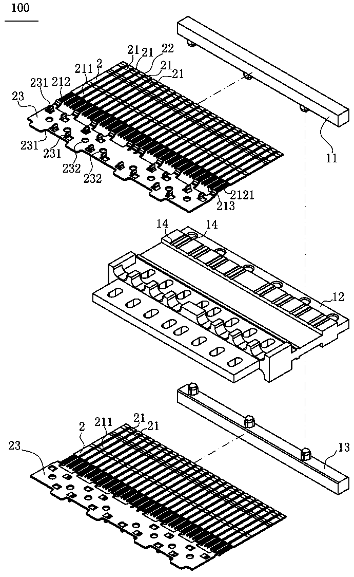
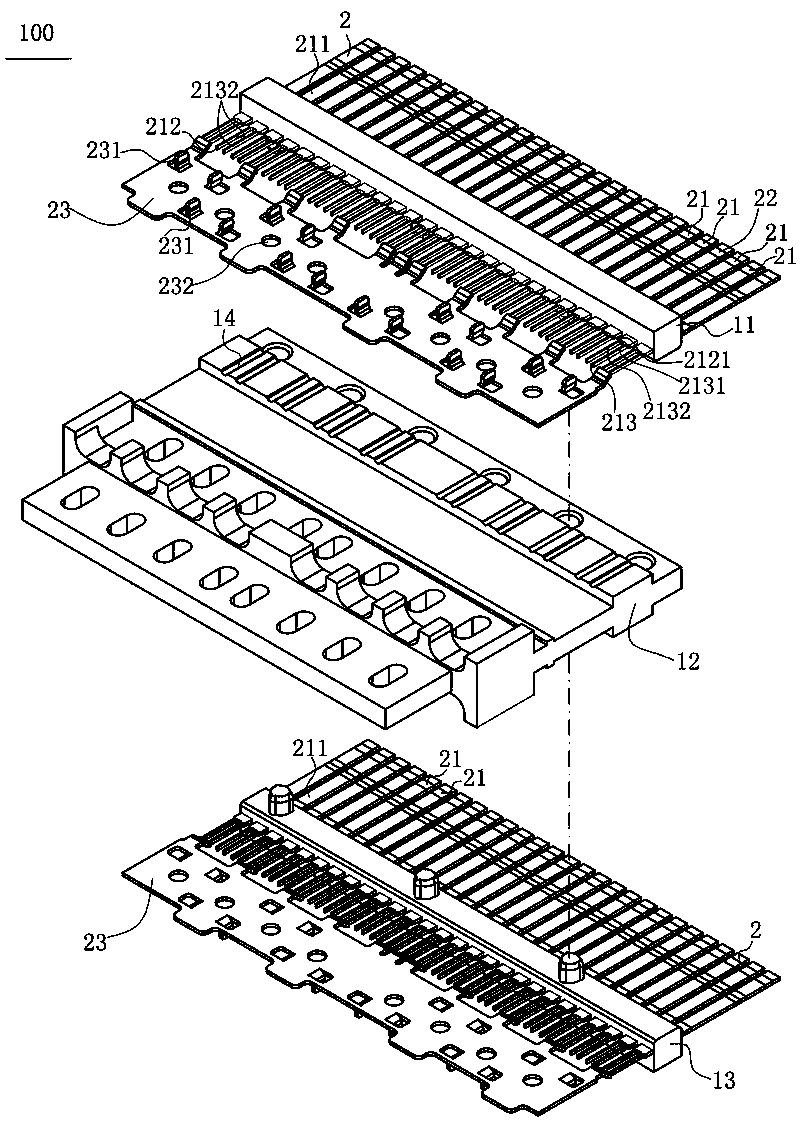
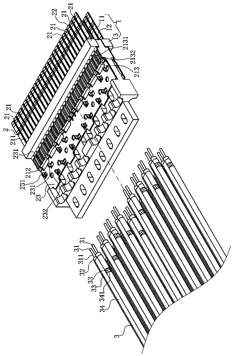
[0032] Such as figure 1 and image 3 As shown, the electrical connector 100 of the present invention includes an insulating body 1 and a plurality of terminals 2 for connecting with a plurality of cables 3 .

[0033] Such as figure 2 and image 3 As shown, the insulating body 1 is assembled from an upper body 11, a middle body 12 and a lower body 13. The rear ends of the three are flush, and the middle body 12 extends forward beyond the upper body 11 and the lower body 13. The middle body 12 The upper surface and the lower surface are respectively provided with a plurality of grooves 14 arranged in a row.

[0034] In other embodiments, the insulating body 1 can be assembled into two pieces only by the upper body 11 and the...


PUM


Abstract

An electrical connector is used for abutting a cable, the cable is provided with a cable core, and the cable core is welded with a welding part. The electrical connector is characterized by comprising an insulation body, wherein a plurality of terminals are arranged on the insulation body, at least one terminal is provided with a contact part, the contact part is forwards exposed out of the insulation body and is provided with a accommodating groove, the accommodating groove vertically penetrates through the contact part and penetrates through a front end of the contact part, the accommodating groove is provided with a rear wall and a side wall, the welding part is arranged in the accommodating groove, a free end of the welding part is stopped at a rear wall, a side surface of the welding part is welded with the side wall by laser, so that a welding effect is convenient to check.

Description

technical field [0001] The invention relates to an electrical connector, especially an electrical connector used for laser welding with a cable. Background technique [0002] In the prior art, the electrical connector has an insulating body, a plurality of terminals are arranged on the insulating body, each terminal has a base for connecting to a circuit board, and a contact portion extending forward from the base for connecting with a The welding part of the cable is laser welded. The contact part and the welding part are usually set up and down opposite each other. After welding, the welding area of ​​the contact part and the welding part is covered by the contact part and the welding part in the vertical direction, so it is difficult to check the welding effect. [0003] Aiming at the above problems, the present invention provides a new electrical connector and adopts new technology to solve these problems. Contents of the invention [0004] Aiming at the problems face...

Claims


Application Information

Patent Timeline
Patent Type & Authority Patents(China)
IPC IPC(8): H01R13/02H01R13/6581H01R9/03H01R4/02
CPCH01R4/029H01R9/03H01R13/02H01R13/6581
Inventor 朱德祥戴拥军
Owner DEYI PRECISION ELECTRONIC IND CO LTD PANYU
Learn More