Movable contact assembly and switch using the same

A technology of moving contacts and switches, applied in the field of movable contact bodies, can solve the problem that the display part 8C cannot be illuminated brightly, etc.

Inactive Publication Date: 2009-04-15
PANASONIC CORP
View PDF0 Cites 8 Cited by
  • Summary
  • Abstract
  • Description
  • Claims
  • Application Information

AI Technical Summary

Problems solved by technology

When the light guide sheet 1 is thin, a sufficient amount of light may not be guided into the light guide sheet 1, and the li

Method used


Image

  • Movable contact assembly and switch using the same
  • Movable contact assembly and switch using the same
  • Movable contact assembly and switch using the same

Examples


Embodiment Construction

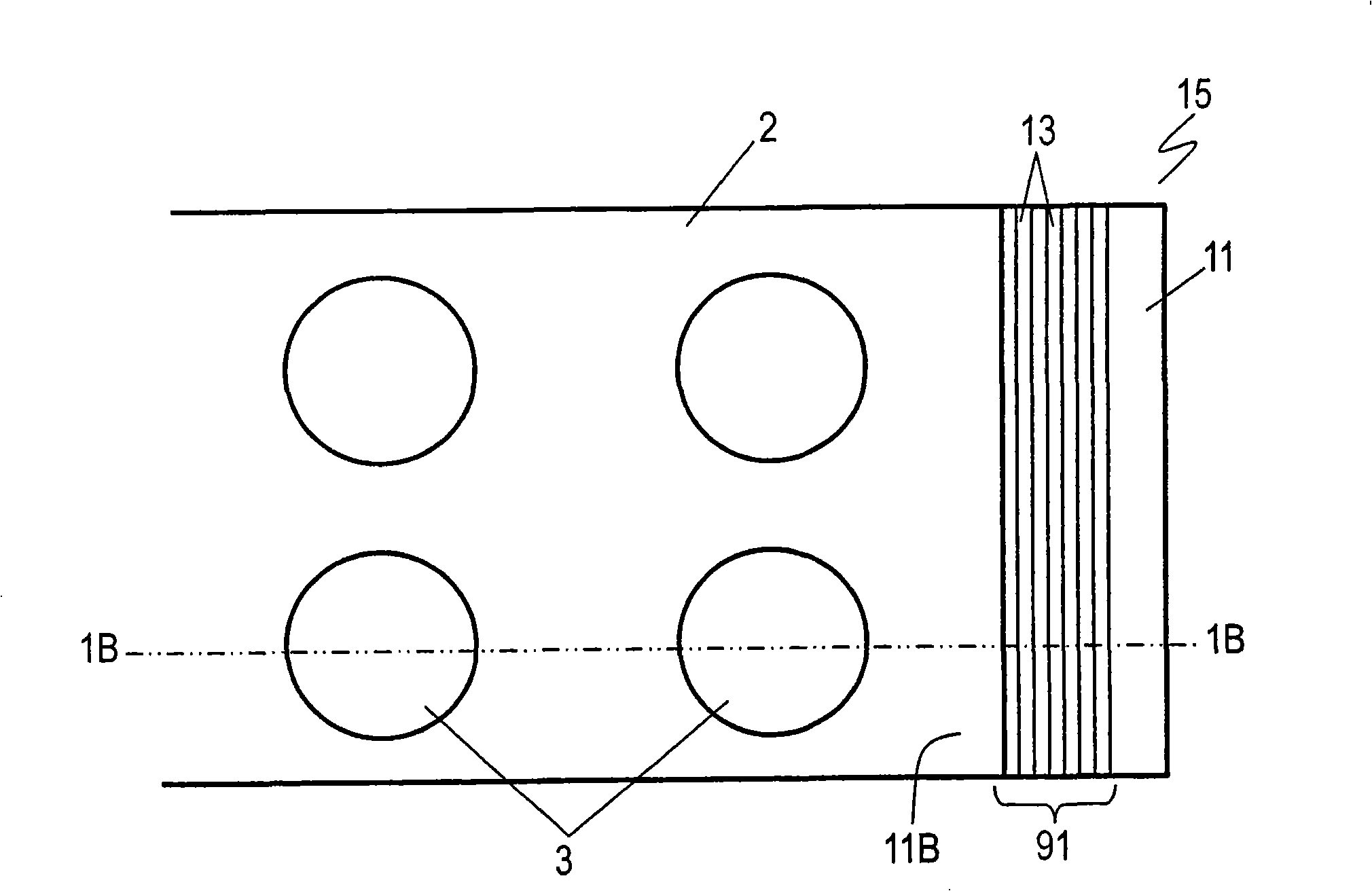
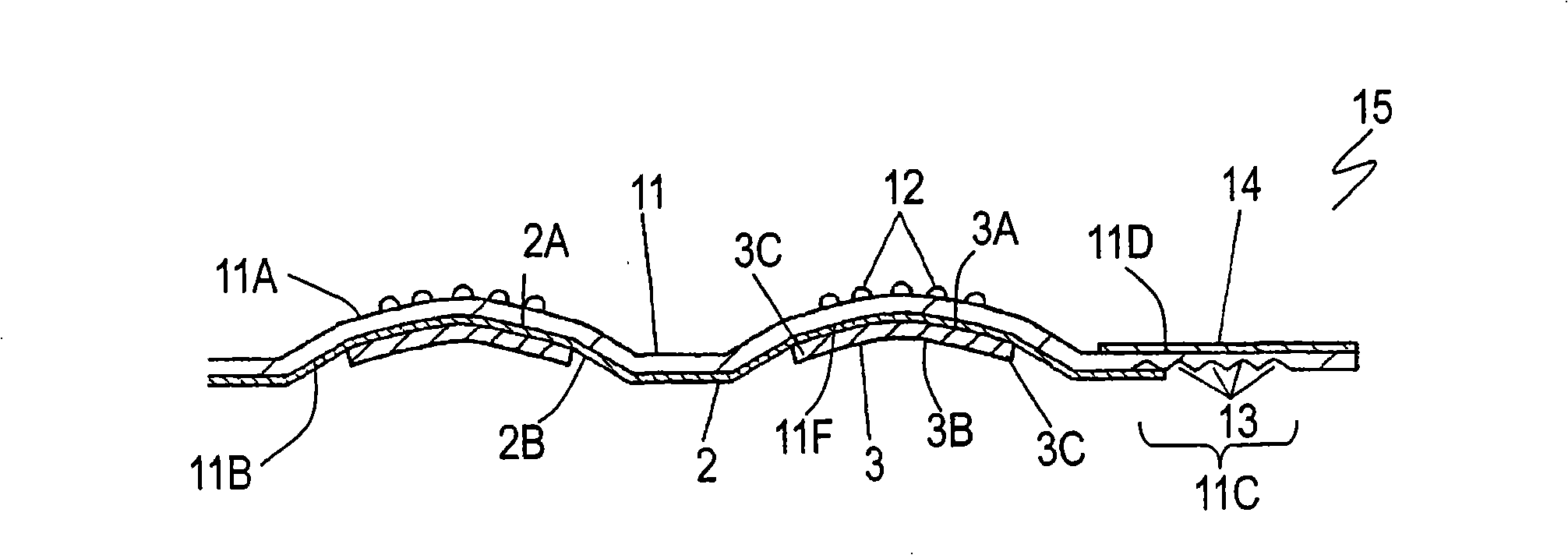
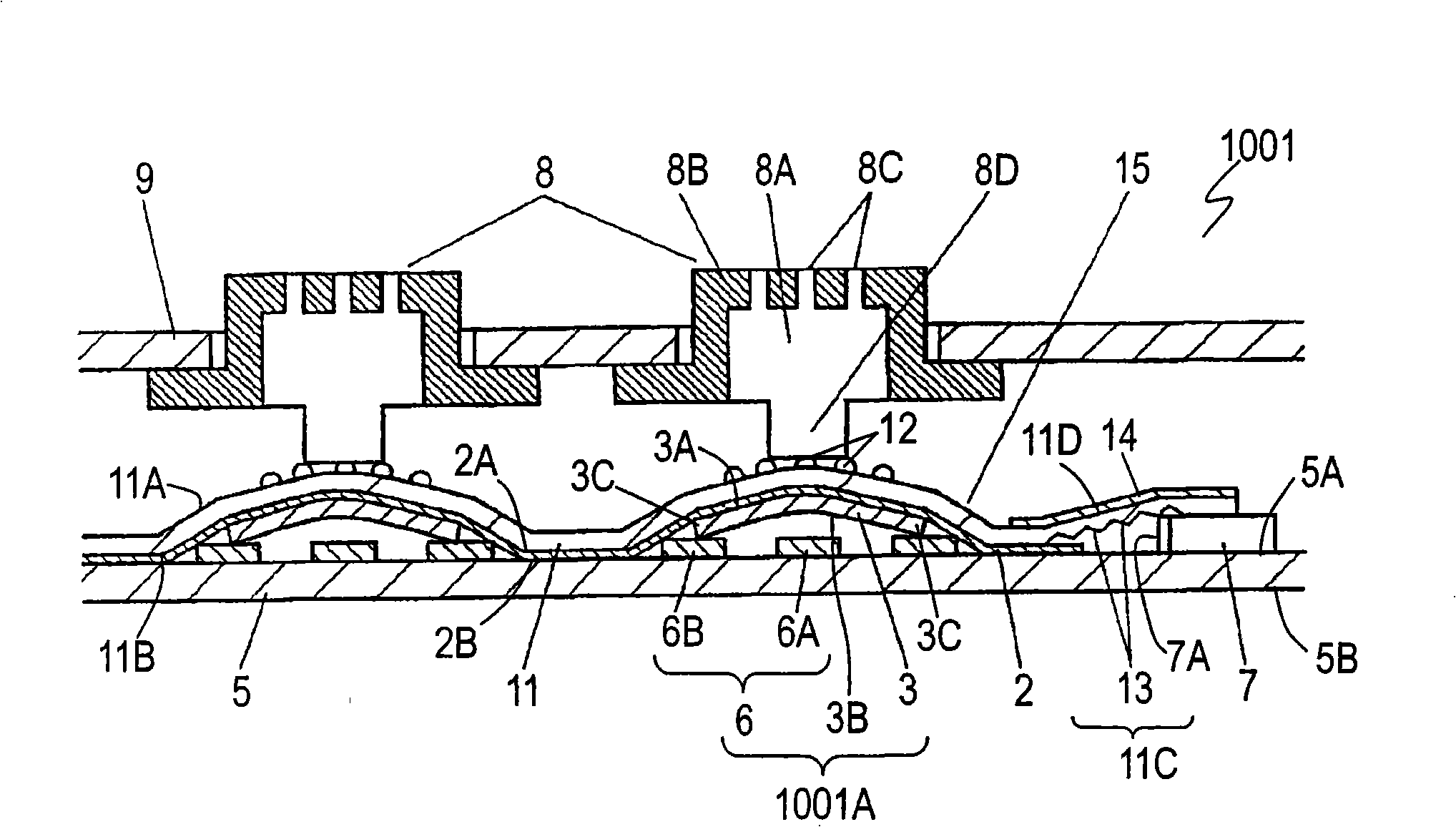
[0028] Figure 1A It is a bottom view of movable contact body 15 according to the embodiment of the present invention. Figure 1B yes Figure 1A A sectional view of the movable contact body 15 taken along line 1B-1B is shown. The light guide sheet 11 is in the form of a film and is made of a flexible light-transmitting member such as polyethylene terephthalate, polycarbonate, polyurethane, or silicone. The light guide sheet 11 has an upper surface 11A and a lower surface 11B opposite to the upper surface 11A. The light guide sheet 11 has a plurality of diffuser portions 12 having a dot shape attached to the upper surface 11A. The diffuser 12 is composed of a transparent resin such as acrylic resin and a white pigment such as titanium oxide dispersed in the transparent resin. The cover sheet 2 is attached to the lower surface 11B of the light guide sheet 11 with an adhesive agent at predetermined positions on the outer periphery of the upper surface 2A of the film-shaped co...


PUM


Abstract

A movable contact assembly includes a light guiding sheet which is light transmittable, and a movable contact provided on the light guiding sheet. The light guiding sheet has a portion having the movable contact provided thereon and a portion having plural grooves provided therein. The grooves constitute a light inlet for introducing light into the light guiding sheet. This movable contact assembly can illuminate a switch preferably with a simple structure, providing the switch with an easily operation.

Description

technical field [0001] The present invention relates to a movable contact body and a switch using the movable contact body. Background technique [0002] In recent years, in various electronic devices, especially mobile terminal devices such as mobile phones, light-emitting diodes, EL elements, etc. The number of components for illuminating the operation portion is increasing. It is required that movable contact bodies and switches used in these devices can be variously illuminated at low cost. [0003] Figure 7 It is a cross-sectional view of a conventional movable contact body 4 . The film-shaped light guide sheet 1 is both light-transmitting and flexible. A plurality of dot-shaped diffusion portions 1A are formed on the upper surface of the light guide sheet 1 . The light guide sheet 1 and the film-like cover sheet 2 are bonded together at predetermined locations on their outer peripheries with an adhesive. [0004] Movable contact 3 is formed of a thin conductive m...

Claims


Application Information

Patent Timeline
IPC IPC(8): H01H13/83
CPCH01H2221/07H01H2219/044H01H2209/082H01H2209/002H01H2219/06H01H2219/062H01H2219/056H01H2205/016H01H13/83
Inventor 田边功二近久阳介相阪勉
Owner PANASONIC CORP
Why Eureka
Try Eureka