Vibrator element, electronic device, electronic apparatus, moving object, and method of manufacturing vibrator element

a technology of vibrator element and manufacturing method, which is applied in the direction of acceleration measurement using interia force, generator/motor, instruments, etc., can solve the problems of difficult use of simple manufacturing device, and achieve the effect of easy electronic device separation, cost reduction, and high functionality

Active Publication Date: 2016-05-05
SEIKO EPSON CORP
View PDF9 Cites 9 Cited by
  • Summary
  • Abstract
  • Description
  • Claims
  • Application Information

AI Technical Summary

Benefits of technology

[0009]According to this application example, the tilted section of the vibrating arm in which the separation section is disposed is exposed toward the obverse surface in the planar view viewed from the obverse surface side, and the side surface electrodes are separated from each other in the tilted section. Therefore, if the so-called plane exposure of applying the light for the exposure toward the plane direction (the obverse and reverse surfaces) of the vibrating arm is used in the exposure for separating the electrodes from each other, it is possible to easily irradiate the tilted section with the light. As described above, in the exposure of the tilted section, it is possible to irradiate the tilted section with the parallel light from the same direction, in other words, to use the plane exposure. Therefore, it becomes possible to use a simple device using the plane exposure, and it is possible to easily perform the exposure (resist exposure) for separating the electrodes from each other.Application Example 2
[0013]According to this application example, there is disposed the drive vibrating arm extending from the base section on the opposite side to the detection vibrating arm. Since the drive vibrating arm and the detection vibrating arm respectively extend from the both end portions of the base section in the same axis direction, the drive system and the detection system are separated from each other to thereby reduce the capacitive coupling between the electrodes or the wiring lines of the drive system and the detection system, and thus, the detection sensitivity of the angular velocity can be stabilized.Application Examples 4 and 5
[0021]According to this application example, the vibrating arm includes the grooves provided respectively to the obverse surface and the reverse surface located on the opposite side to the obverse surface, the side surface electrodes disposed on the side surface adapted to connect the obverse surface and the reverse surface to each other, and the groove electrodes provided to the grooves. Further, there is provided the outer circumferential shape in which the tilted section exposed toward the obverse surface is included in at least a part of the side surface. Further, in the dividing, the side surface electrode film is divided inside the tilted section, and the groove electrode film is divided inside the groove. Since the side surface electrode film is divided inside the tilted section as described above, if the so-called plane exposure of applying the light for the exposure toward the plane direction (the obverse and reverse surfaces) of the vibrating arm is used in the applying of light as a part of the dividing, it is possible to easily irradiate the tilted section with the light. Further, at the same time, the inside of the groove can easily be irradiated with the light by the plane exposure. As described above, it becomes possible to use the simple device using the plane exposure of irradiating the tilted section with the parallel light from the same direction in the exposure including the tilted section, and it is possible to easily perform the exposure (resist exposure) for separating the electrodes from each other.Application Example 11
[0029]According to these application examples, since there is provided the vibrator element according to any one of the application examples described above in which the electrode separation can easily be achieved, namely the cost reduction is achieved, the low-cost moving object can be provided. Further, since the electronic device is equipped with the highly sensitive vibrator element on which the adjustment for suppressing the leakage output is performed, the moving object, which is highly functional, and has stable characteristics, can be provided.

Problems solved by technology

However, since the electrode film to be divided is disposed on the side surface formed roughly perpendicularly to the obverse and reverse surfaces of such a detection vibrating arm as described above, it has been difficult to use a simple manufacturing device such as a so-called plane exposure device for irradiating the obverse and reverse surfaces of the detection vibrating arm with light in a vertical direction in the exposure process for forming separation sections.

Method used


Image

  • Vibrator element, electronic device, electronic apparatus, moving object, and method of manufacturing vibrator element
  • Vibrator element, electronic device, electronic apparatus, moving object, and method of manufacturing vibrator element
  • Vibrator element, electronic device, electronic apparatus, moving object, and method of manufacturing vibrator element

Examples


first embodiment

Vibrator Element-1

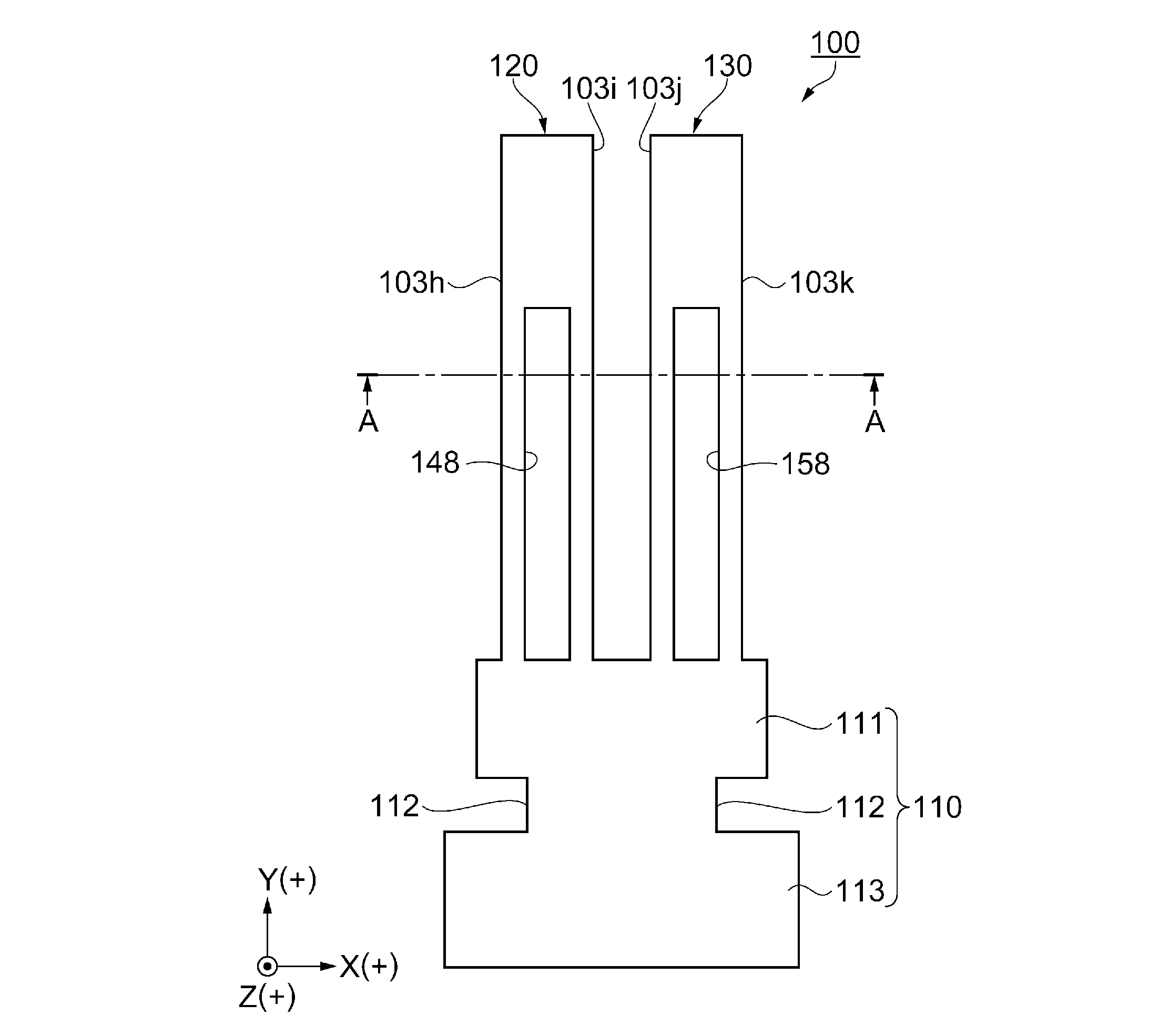
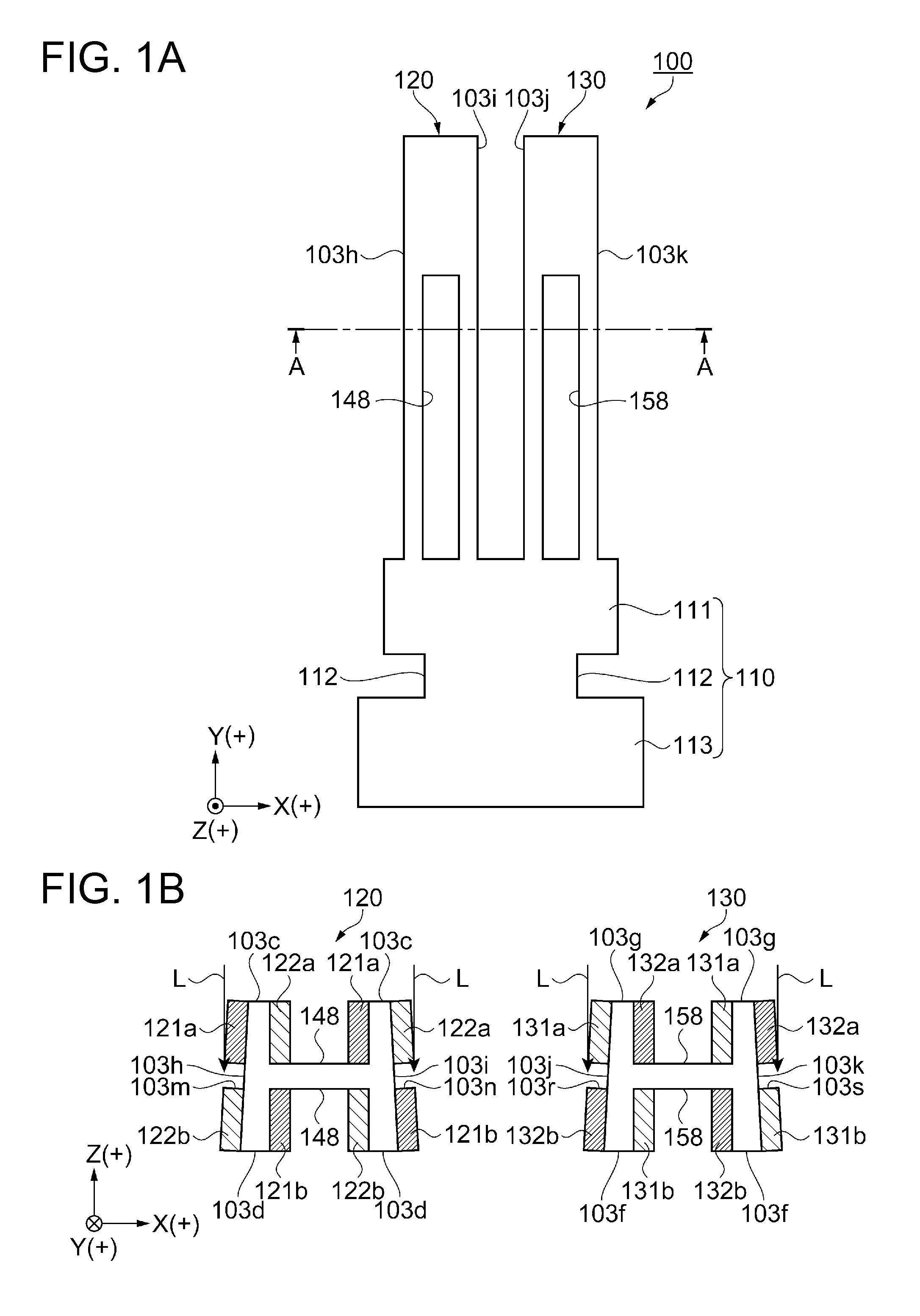
[0043]Firstly, a schematic configuration of the vibrator element according to a first embodiment will be explained using FIGS. 1A and 1B. FIG. 1A is a plan view schematically showing a general configuration of a tuning fork vibrating element as the vibrator element according to the first embodiment. FIG. 1B is a cross-sectional view along the A-A line in FIG. 1A. It should be noted that in FIG. 1A, drive electrodes are omitted for the sake of convenience of explanation.

[0044]As shown in FIGS. 1A and 1B, the tuning fork vibrating element 100 as the vibrator element is a tuning fork vibrating element provided with a base section 110, and drive vibrating arms 120, 130 as a pair of vibrating arms extending in the +Y-axis direction from the base section 110. The base section 110 has a plate-like shape provided with a narrow-width section 111 and a wide-width section 113 disposed via a constricted section 112. It should be noted that it is possible for the base section 1...

second embodiment

Vibrator Element-2

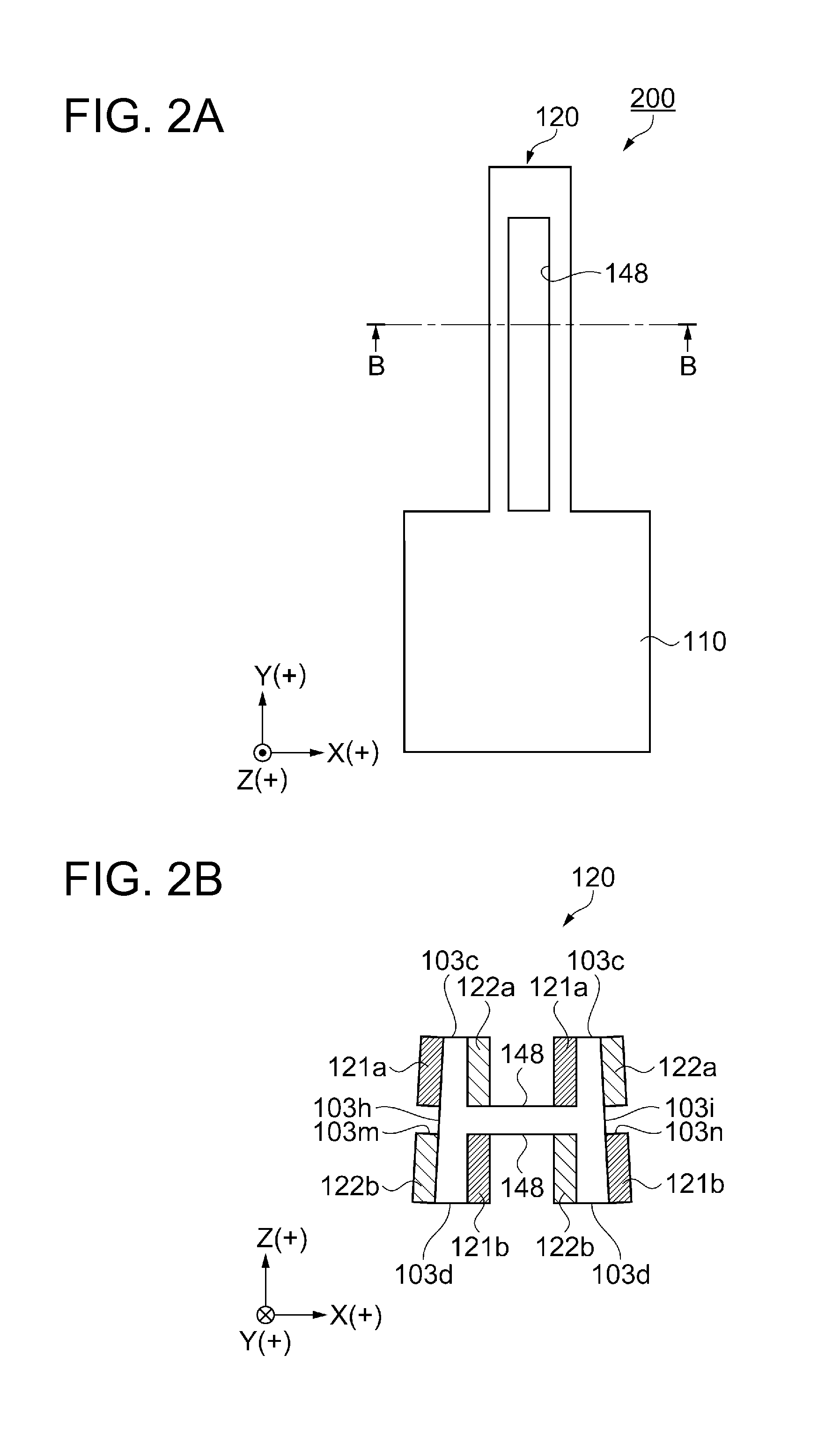
[0060]Then, a vibrator element according to a second embodiment will be explained with reference to FIGS. 2A and 2B.

[0061]FIGS. 2A and 2B are diagrams schematically showing a general configuration of a flexural vibrating element as a vibrator element according to the second embodiment, wherein FIG. 2A is a plan view, and FIG. 2B is a cross-sectional view along the B-B line of FIG. 2A.

[0062]Firstly, a general configuration of the vibratory element according to the second embodiment will be explained. It should be noted that the flexural vibrating element 200 as the vibratory element according to the present second embodiment is provided with the drive vibrating arm 120 as the vibrating arm having the same configuration as that of the tuning fork vibrating element 100 described as the first embodiment. The same constituents as those of the tuning fork vibrating element 100 according to the first embodiment are denoted with the same reference numerals, and the duplica...

third embodiment

Gyro Element-1

[0072]Firstly, a gyro element as a vibrator element according to a third embodiment of the invention will be explained with reference to FIGS. 3A, 3B, 4, 5A, and 5B. FIGS. 3A and 3B are diagrams showing the gyro element as the embodiment, wherein FIG. 3A is a perspective view schematically showing the gyro element, and FIG. 3B is a plan view schematically showing the gyro element. FIG. 4 is a diagram showing the detection vibrating arms of the gyro element in an enlarged manner, and is a partial plan view of the region Q shown in FIG. 3B. FIGS. 5A and 5B are diagrams for explaining an electrode configuration of the gyro element, wherein FIG. 5A is a cross-sectional view along the C-C line in FIG. 3B, and FIG. 5B is a cross-sectional view along the D-D line in FIG. 3B.

[0073]As shown in FIG. 3A, the gyro element 300 according to the third embodiment has a base section 1 integrally formed by processing a base material (a material constituting an essential part), drive vib...


PUM


Abstract

A vibrator element includes drive vibrating arms extending from an end of a base section, the drive vibrating arms are each provided with an obverse surface, a reverse surface disposed on an opposite side to the obverse surface, and a side surface connecting the obverse surface and the reverse surface to each other, a tilted section facing toward the obverse surface is disposed at least a part of the side surface, and there are disposed a first drive electrode and a second drive electrode obtained by bisection with an electrode separation section disposed in the tilted section.

Description

BACKGROUND[0001]1. Technical Field[0002]The present invention relates to a vibrator element, and an electronic device, an electronic apparatus, and a moving object using the vibrator element, and a method of manufacturing the vibrator element.[0003]2. Related Art[0004]For small-sized information equipment such as a mobile computer or an IC card, mobile communication equipment such as a cellular phone, and vehicle control and a vehicle position detection, a vibration control correction function (so-called image stabilization) for digital cameras or digital video camera, and so on, vibrators using a vibrator element and gyro sensors are used widely. For example, the gyro sensor detects an electric signal, which is generated in a part of a gyro vibrator element (a gyro vibrating element) due to a vibration such as a tremor or a rotation of an object, as an angular velocity using the gyro vibrating element, and then obtains the displacement of the object by calculating the rotational an...

Claims


Application Information

Patent Timeline
Patent Type & Authority Applications(United States)
IPC IPC(8): H03H9/21G01C19/5607H03H3/02
CPCH03H9/21H03H2003/026G01C19/5607H03H3/02
Inventor NAKAGAWA, KEIJINISHIZAWA, RYUTAMATSUO, ATSUSHI
Owner SEIKO EPSON CORP
Why Eureka
Try Eureka