A pipe clamping device for an industrial robot

A technology of industrial robots and clamping devices, applied in the direction of conveyor objects, chucks, manipulators, etc., can solve the problems of difficult control of the center of gravity of pipe fittings, insufficient stability of pipe clamping, and complex design structures, etc., to achieve clamping safety Reliable, reduced quantity, work safe and reliable effect

Active Publication Date: 2018-08-31
TAIZHOU HONGXIANG POWER MACHINERY
View PDF9 Cites 0 Cited by
  • Summary
  • Abstract
  • Description
  • Claims
  • Application Information

AI Technical Summary

Problems solved by technology

[0002] In the production and manufacturing process of pipe fittings, it is often necessary to carry pipe fittings. Nowadays, industrial robots are usually used for handling to effectively reduce manpower. When industrial robots carry pipe fittings, they need to be clamped first. The design of traditional clamping devices The structure is complex, the manufacturing cost is high, and the stability of the clamping of the pipe fittings is not enough, it is difficult to control the position of the center of gravity of the pipe fittings, and the risk of the pipe fittings being easily dropped from the clamping device during the handling process, so the clamping used by traditional industrial robots During the handling of the device, there are certain potential safety hazards

Method used


Image

  • A pipe clamping device for an industrial robot
  • A pipe clamping device for an industrial robot
  • A pipe clamping device for an industrial robot

Examples


Embodiment Construction

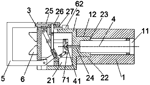
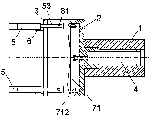
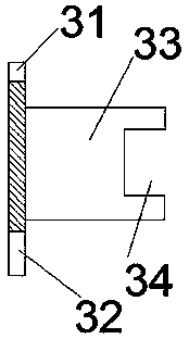
[0031] Such as Figure 1-Figure 12 As shown, a pipe fitting clamping device for an industrial robot of the present invention includes a joint 1 connected to the mechanical arm of the industrial robot, and a second space fixed at the left end of the joint 1 and provided with an opening to the left. The cavity 21, the upper surface is provided with a rectangular groove 25 and the right side of the second cavity 21 directly below the rectangular groove 25 is provided with a seat body 2 of a narrow and long through groove 27, and the seat body 2 in the middle of the rectangular groove 25 A rectangular hole 26 in the up and down direction is arranged on the top, a cover plate 3 fixedly mounted on the left end of the seat body 2 and extending rightward into the second cavity 21, two sets of connecting rod groups, and a driving cylinder 4 , and two U-shaped mechanical claws 5, and an iron stop assembly installed on the upper surface of the seat body 2 on the right side of the narrow ...


PUM


Abstract

The invention discloses a pipe clamping device for an industrial robot. The pipe clamping device comprises a connector, a second cavity, a base body, a vertical rectangular hole, a cover plate, two connecting rod sets, a driving cylinder, two U-shaped mechanical paws, an iron blocking assembly and two V-shaped blocks, wherein the connector is connected with a mechanical arm of the industrial robot; the second cavity is fixed to the left end of the connector and provided with a leftward opening; the upper surface of the base body is provided with a rectangular groove, and a long and narrow slot is formed in the position, under the rectangular groove and on the right side of the second cavity, of the base body; the rectangular hole is formed in the position, located in the middle of the rectangular groove, of the base body; the cover plate is fixedly mounted at the left end of the base body and extends rightwards into the second cavity; the iron blocking assembly is mounted on the upper surface of the base body and located on the right side of the long and narrow slot; the two V-shaped blocks are fixed to the left side face of the cover plate. The pipe clamping device adopts pneumatic control, is convenient to operate, can realize closing and locking of the mechanical paws by using one cylinder, reduces the manufacturing cost and is safe and reliable in clamping.

Description

technical field [0001] The invention relates to a pipe fitting clamping module, in particular to a pipe fitting clamping device for an industrial robot. Background technique [0002] During the production and manufacturing process of pipe fittings, it is often necessary to carry pipe fittings. Nowadays, industrial robots are usually used for handling to effectively reduce manpower. When industrial robots carry pipe fittings, they need to be clamped first. The design of traditional clamping devices The structure is complex, the manufacturing cost is high, and the stability of the clamping of the pipe fittings is not enough, it is difficult to control the position of the center of gravity of the pipe fittings, and the risk of the pipe fittings being easily dropped from the clamping device during the handling process, so the clamping used by traditional industrial robots During the transportation of the device, there are certain potential safety hazards. Contents of the inven...

Claims


Application Information

Patent Timeline
Patent Type & Authority Patents(China)
IPC IPC(8): B25J15/08B65G47/90
CPCB25J15/08B65G47/90
Inventor 李明
Owner TAIZHOU HONGXIANG POWER MACHINERY
Why Eureka
Try Eureka