
Installation construction method of kitchen and bath drainage pipes

A construction method and technology of drainage pipes, which are applied in the direction of water supply devices, sewer pipe systems, waterway systems, etc., can solve the problems of bad influence of residents, water leakage of kitchen and bathroom pipes, and low connection rate between pipe floors, so as to avoid socket depth Insufficient, reduce the time of positioning, and facilitate the effect of curly storage

Inactive Publication Date: 2017-11-28
王慧玲
View PDF0 Cites 0 Cited by
  • Summary
  • Abstract
  • Description
  • Claims
  • Application Information

AI Technical Summary

Problems solved by technology

[0002] In the prior art, when installing and locating kitchen and bathroom drainage pipes, it is necessary to measure the location of the pipes on each floor to determine the location of the drainage pipes and install them. The connection rate is low, which may easily cause loosening of the pipe joints and water seepage
[0003] When installing the kitchen and bathroom drainage pipes, the kitchen and bathroom pipes are mostly cut and assembled on site, and the U-PVC drainage pipes are installed in multiple water spaces, and the process of leaving holes first and then installing is used. After filling the holes, the pipe roots are easy to seep Leakage, causing water leakage in the kitchen and bathroom pipes, causing adverse effects on residents

Method used


Image

  • Installation construction method of kitchen and bath drainage pipes
  • Installation construction method of kitchen and bath drainage pipes

Examples


Embodiment 1

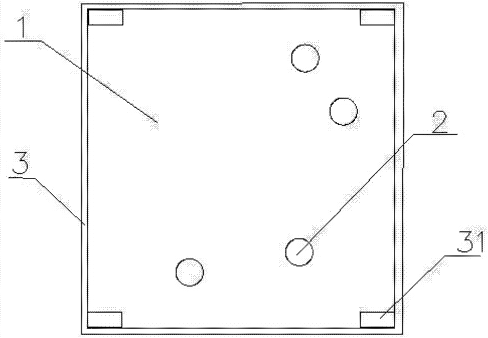
[0023] Such as figure 2 The lofting blanket shown includes a flexible plane 1 made of polyvinyl chloride resin material, and, arranged on the flexible plane, a plurality of positioning holes 2 adapted to a plurality of water-stop joints; wherein, the lofting The edge of the blanket is also provided with a positioning edge 3 for positioning it on the template, and a positioning clip 31 is provided on the positioning edge 3 .

Embodiment 2

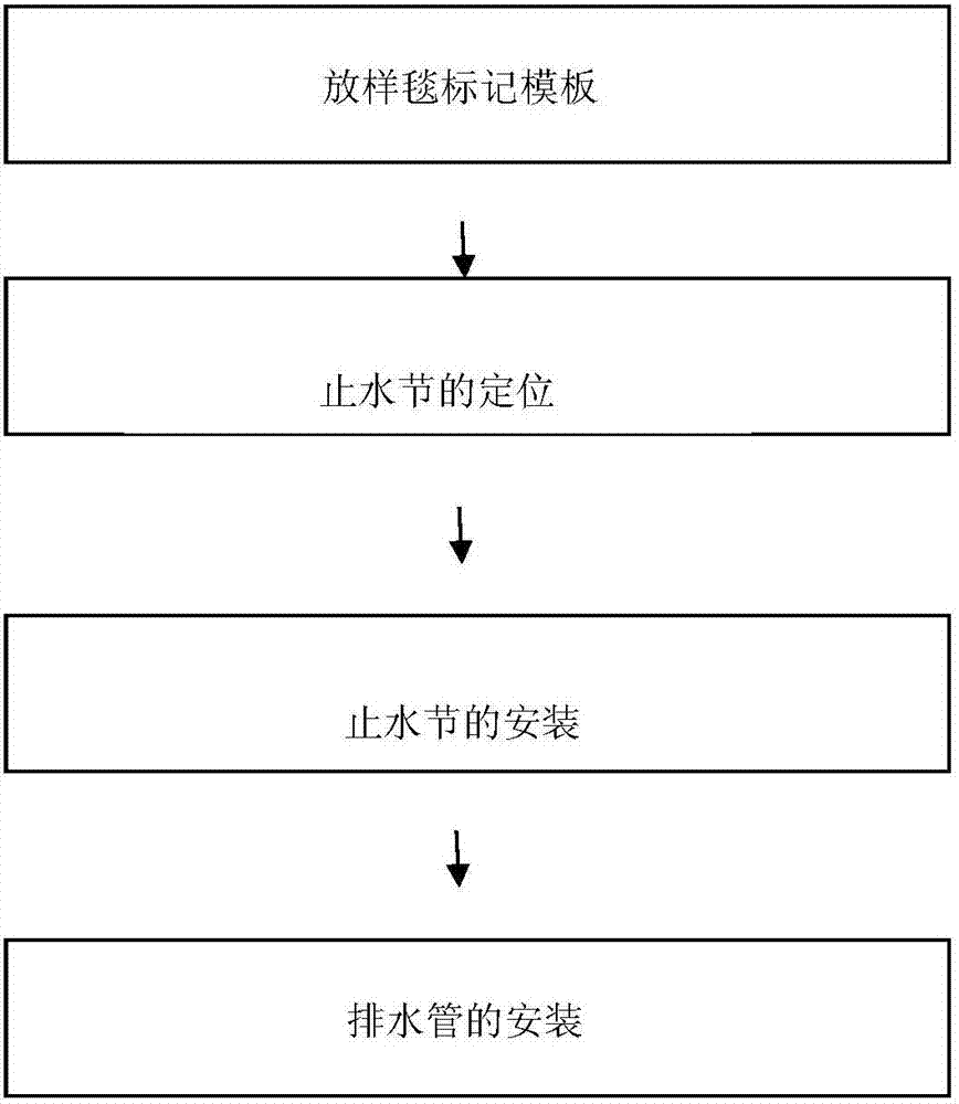
[0025] Installation and construction of drainage pipes

[0026] 1. Stakeout blanket marking template

[0027] Use straightedge (other length measuring instruments are equally applicable to the present invention) to measure the length and width of the bathroom floor, the diameter of the water stop and the size of the water stop in the layout design position of the template; according to the measured size data, correspondingly cut the lofting blanket, Make the stakeout blanket have the same size as the template, and mark the position of the water stop section on the stakeout blanket; leave blanks on the stakeout blanket according to the marked water stop section position, so that the marked water stop section position on the stakeout blanket leave blank.

[0028] The use of lofting blankets can quickly and accurately locate the pre-buried water-stop joints used for the installation of kitchen and bathroom drainage risers on the same vertical surface of the same building, avoidi...


PUM


Abstract

The invention provides an installation construction method of drainage pipes. The installation construction method comprises the following steps that a lofting blanket is adopted to mark a template, positioning is conducted on waterstop sections, and concrete pouring is conducted. The waterstop sections and the drainage pipes are installed. According to the installation construction method of the drainage pipes, the drainage pipes between the upper and the lower kitchens and the bathes of the same vertical plane of the same building can be installed rapidly and accurately, a drainage pipe connection deviation caused by a positioning deviation of the pre-buried waterstop sections is avoided, the bearing and inserting depth of each drainage pipe is marked through marking lines and marking rings, pipeline installation is compact, and water leakage does not occur; and in the installing process, the visual management of the bearing and inserting depth is conducted effectively, water leakage caused by the insufficient bearing and inserting depth of pipeline connectors due to the fact that insufficiency of the bearing and inserting depth cannot be inspected in the construction process is avoided, the installation efficiency is high, and both time and labor are saved.

Description

technical field [0001] The invention relates to the field of building construction, in particular to the construction of drainage pipes. Background technique [0002] In the prior art, when installing and locating kitchen and bathroom drainage pipes, it is necessary to measure the location of the pipes on each floor to determine the location of the drainage pipes and install them. The low connection rate may easily cause loosening of the pipe joints and water seepage. [0003] When installing the kitchen and bathroom drainage pipes, the kitchen and bathroom pipes are mostly cut and assembled on site, and the U-PVC drainage pipes are installed in multiple water spaces, and the process of leaving holes first and then installing is used. After filling the holes, the pipe roots are easy to seep Leakage, resulting in leakage of kitchen and bathroom pipes, causing adverse effects on residents. Contents of the invention [0004] The purpose of the present invention is to overco...

Claims


Application Information

Patent Timeline
Patent Type & Authority Applications(China)
IPC IPC(8): E03F3/06
CPCE03F3/06
Inventor 王慧玲
Owner 王慧玲
Learn More