
polarizing element

A polarizing element and established technology, applied in polarizing elements, optical elements, instruments, etc., can solve the problems of difficulty in maintaining reliability and high difficulty, and achieve the effect of improving light transmission characteristics

Active Publication Date: 2020-03-10
DEXERIALS CORP
View PDF10 Cites 0 Cited by
  • Summary
  • Abstract
  • Description
  • Claims
  • Application Information

AI Technical Summary

Problems solved by technology

It is known that the transmittance can be improved by reducing the grid width of the polarizing element, but actually it is difficult to form a pattern with narrowed grid width and it is also difficult to maintain reliability

Method used


Image

  • polarizing element
  • polarizing element
  • polarizing element

Examples


Embodiment Construction

[0046] Hereinafter, embodiments of the present invention will be described with reference to the drawings.

[0047]

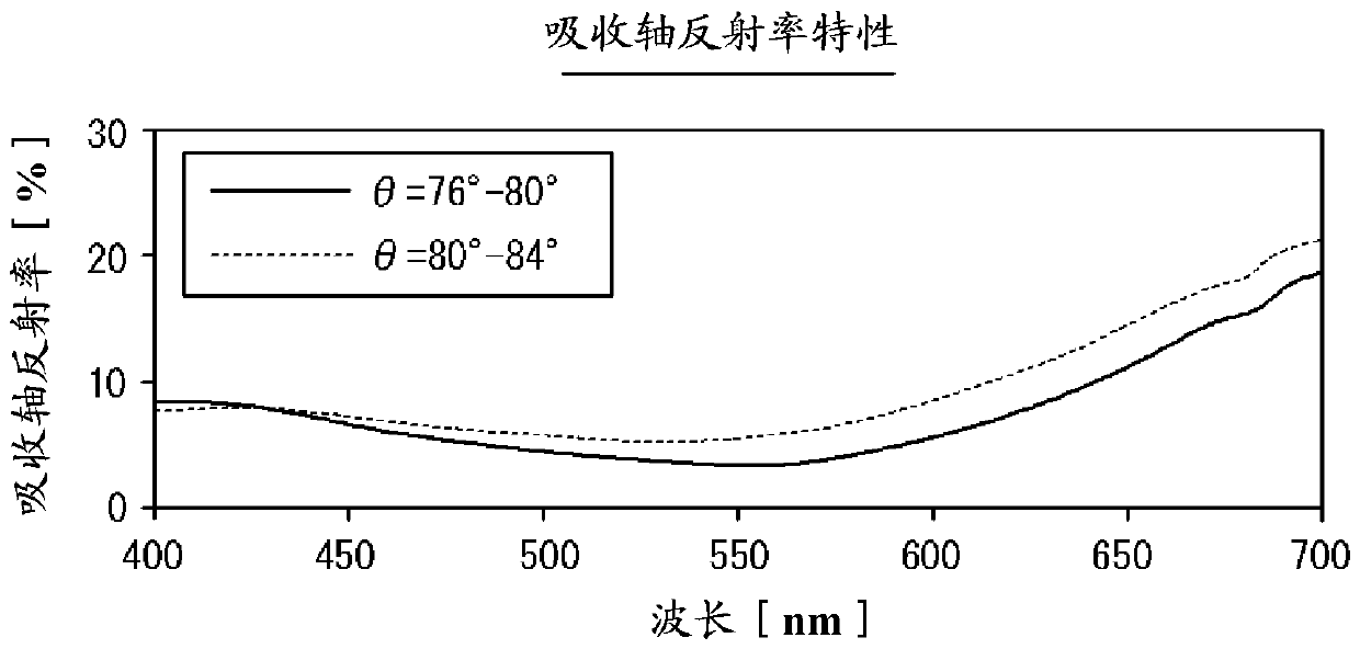
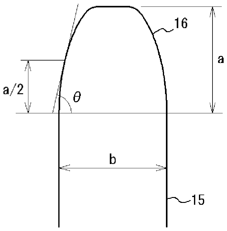
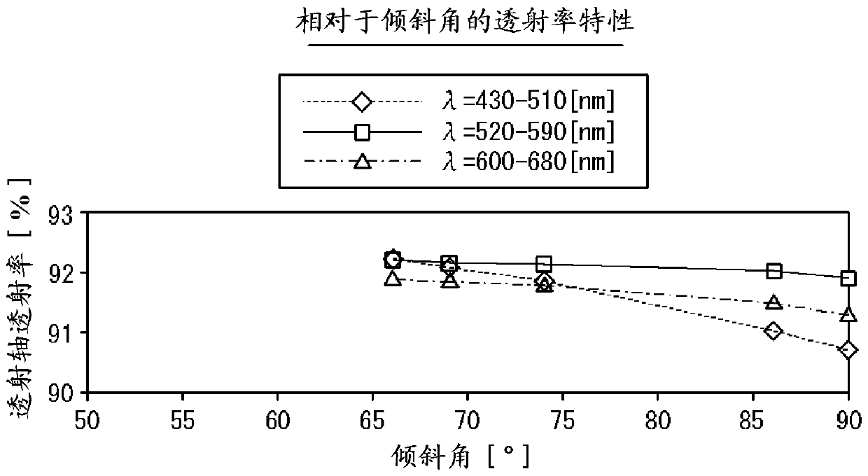
[0048] figure 1 It is a schematic cross-sectional view showing the polarizing element 1 according to one embodiment of the present invention. like figure 1As shown, the polarizing element 1 includes a transparent substrate 11 that is transparent to light in the wavelength band used; and a reflection layer that constitutes the lattice-shaped convex portions 10 arranged on one surface of the transparent substrate 11 at a pitch smaller than the wavelength of the light in the wavelength band used. 12. A dielectric layer 13 formed on the reflective layer 12 and an absorption layer 14 formed on the dielectric layer 13. That is, the polarizing element 1 has a one-dimensional grid-shaped wire grid in which the reflective layer 12 , the dielectric layer 13 and the absorption layer 14 are stacked in this order from the transparent substrate 11 side, and the grid-shap...


PUM

PropertyMeasurementUnit
reflectanceaaaaaaaaaa
refractive indexaaaaaaaaaa

Abstract

A polarizing element includes: a transparent substrate; and grid-shaped convexities that are arranged on the transparent substrate at a smaller pitch than a wavelength of operating band light and that extend in a specific direction. The grid-shaped convexities include a reflection layer formed on the transparent substrate and grid tips formed with side surfaces that, when viewed in the specific direction, are inclined in a direction of tip tapering.

Description

[0001] Cross-reference of related applications [0002] This application claims priority based on Japanese Patent Application No. 2015-093351 (filed on April 30, 2015), and the entire disclosure of this application is incorporated herein for reference. technical field [0003] The present invention relates to a polarizing element having a wire grid configuration. Background technique [0004] The polarizer is an optical element that absorbs polarized light in one direction and transmits polarized light in a direction perpendicular to it. In a liquid crystal display device, a polarizing element is required in principle. In particular, in a liquid crystal display device that uses a light source with a large amount of light, such as a transmissive liquid crystal projector, the polarizing element receives strong radiation, so excellent heat resistance is required, and a size of several centimeters and a relatively small size are required. High extinction ratio. A wire grid-ty...

Claims


Application Information

Patent Timeline
Patent Type & Authority Patents(China)
IPC IPC(8): G02B5/30
CPCG02B5/3058G02B5/3066
Inventor 武田吐梦
Owner DEXERIALS CORP
Learn More