Mouse capturing device

A mousetrap and shell technology, which is applied in the field of mousetrap, can solve the problems of low mousetrap efficiency, inability to guarantee the success rate of mousetrap, and large retracting distance of movable clips, so as to achieve easy capture, improve mousetrap efficiency, and good mouse effect

Pending Publication Date: 2017-12-01
杨守强
View PDF8 Cites 1 Cited by
  • Summary
  • Abstract
  • Description
  • Claims
  • Application Information

AI Technical Summary

Problems solved by technology

[0003] Existing mousetrap varieties are various, and all can not effectively solve the rodent problem, for example, the angle between the base of the existing mousetrap and the movable clip is 180 degrees, the retraction distance of the movable clip is large, and the efficiency of mouse catching is large. Not high; another method of sticking mice with glue is to catch mice by the stickiness of the glue, but the success rate of catching mice cannot be guaranteed due to problems such as dust in the glue itself; and killing mice with drugs and electricity Because of its low safety factor, the method has been expressly prohibited or strictly prohibited. Therefore, people generally use mouse traps to catch mice. In the past, the simplest structure of mouse traps was: including the base plate and the splint set on the base plate. And the trigger plate set on the splint, when the mouse steps on the trigger plate, the splint will be closed immediately to catch the mouse
[0004] However, the mousetrap in the prior art only has the function of not catching, but because the prevention of the mousetrap is not for a short time, but for a long time, the mousetrap is also a work of two days a day, but a long time. Due to the long time, many users will forget where the mousetrap is placed, and after catching the mouse, the mousetrap cannot send out a signal independently, and it is very often to find the source of the stench after the mouse's corpse stinks. will be found

Method used


Image

  • Mouse capturing device
  • Mouse capturing device
  • Mouse capturing device

Examples


Embodiment Construction

[0022] The present invention will be further described below in conjunction with specific embodiments and accompanying drawings.

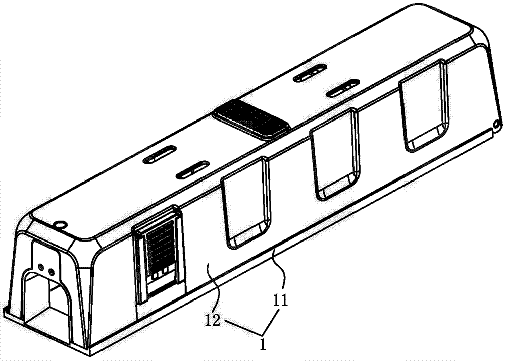
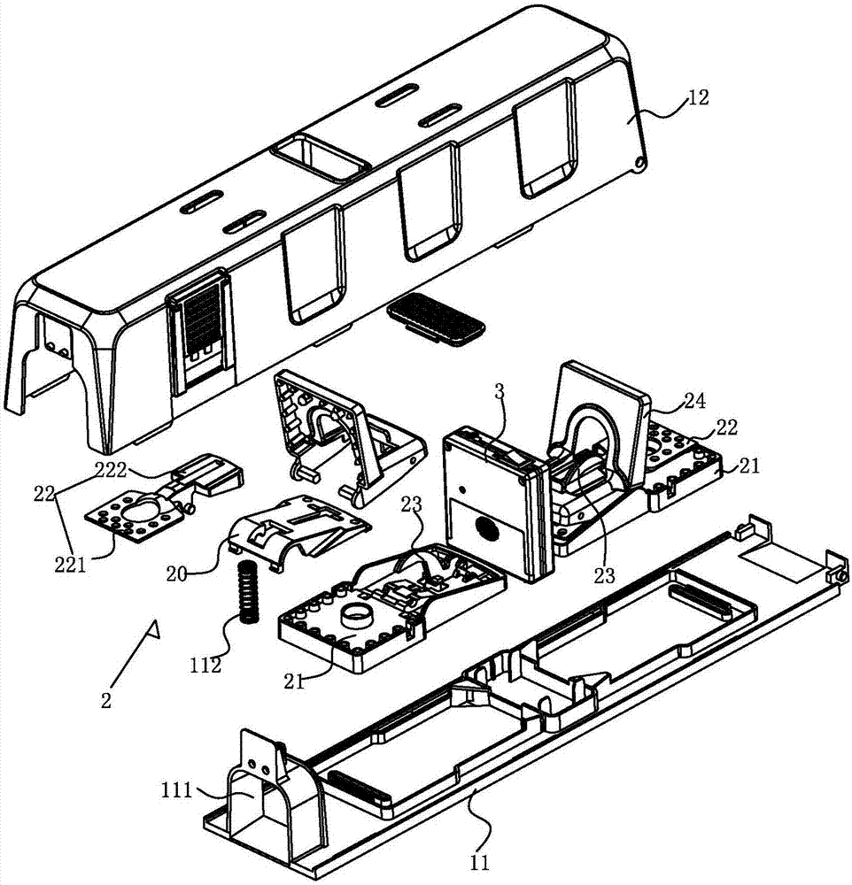
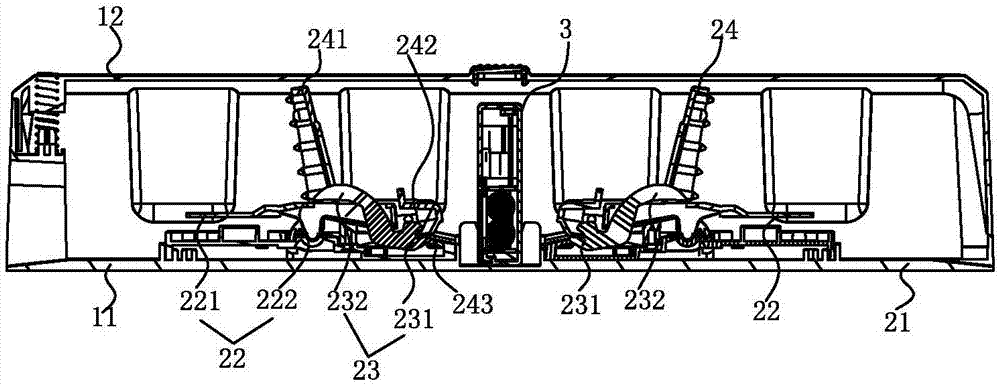
[0023] See Figure 1-4 As shown, the mouse catching device has a shell 1, a mouse trap cavity is formed in the shell 1, an entrance communicating with the mouse trap cavity is formed on the shell 1, and a mouse trap 2 and a vibration trap are installed in the mouse trap cavity corresponding to the entrance. sensor3.

[0024] The shell 1 includes: a bottom shell 11 and a face shell 12, the bottom shell 11 and the face shell 12 can be made of metal material or plastic material, the bottom shell 11 is integrally injected to form a door frame 111, and the opening in the door frame 111 forms the described At the entrance, a spring 112 is set on the top of the door frame 111, and the bottom shell 11 and the face shell 12 are correspondingly provided with a clamping hole and a clamping column, and the clamping and exiting the clamping hole is the same, a...


PUM


Abstract

The invention discloses a mouse capturing device. The mouse capturing device has a housing; a mouse capturing cavity is formed in the housing; a mouse capturing clamp and a vibration sensor are arranged in the mouse capturing cavity; the mouse capturing clamp includes a bottom plate, a movable plate arranged on the bottom plate, a trigger plate connected to the movable plate, and a clamping plate matching the bottom plate; the movable plate includes a pedal plate and a pressing plate connected to the pedal plate; and the vibration sensor includes a housing, a circuit board arranged in the housing, a vibration sensor body, a buzzer, and a light emitting LED. The mouse capturing device is good in mouse capturing effect, and can improve the efficiency of mouse capturing; the mouse capturing clamp is positioned in the housing, a motion space is reduced after a mouse enters the housing, and the mouse can be easily captured; the vibration sensor body is arranged in the housing, can give an alarm sound and emit light after the mouse is captured, can inform a user of the fact that the mouse is captured, and can remind the user to timely process the captured mouse; and the light source can help the user to search the position of the vibration sensor.

Description

Technical field: [0001] The invention relates to the technical field of mousetrap, in particular to a mousetrap device with a shock sensor. Background technique: [0002] Rats are one of the four most closely related to human beings. Since humans began to settle down, farm and have a home, rats have been attached to humans for a living, and they have always endangered humans. There are many kinds of rodents, huge numbers, and strong adaptability. They have been uninvited and unwelcome "guests" of human beings since ancient times. It warns us that we must resolutely eradicate rats. [0003] Existing mousetrap varieties are various, and all can not effectively solve the rodent problem, for example, the angle between the base of the existing mousetrap and the movable clip is 180 degrees, the retraction distance of the movable clip is large, and the efficiency of mouse catching is large. Not high; another method of sticking mice with glue is to catch mice by the stickiness of ...

Claims


Application Information

Patent Timeline
Patent Type & Authority Applications(China)
IPC IPC(8): A01M23/26G08B21/24
CPCA01M23/26G08B21/24
Inventor 杨守强
Owner 杨守强
Why Eureka
Try Eureka