Mechanical arm system with conveying function

A technology of robotic arms and functions, applied in the field of robotic arms, to achieve the effect of easy grasping

Pending Publication Date: 2017-12-01
肇庆市小凡人科技有限公司
5 Cites 2 Cited by

AI-Extracted Technical Summary

Problems solved by technology

However, there are few successful product attempts. The reason is that it is difficult to have uniform standards for containers and tableware used in the catering industry, and in order to attr...

Abstract

The invention relates to a mechanical arm system with the conveying function. The mechanical arm system comprises a transversely arranged sliding rail, a sliding end which is matched with the sliding rail, a lifting part which is telescopically arranged in the sliding end, a grabbing part which is arranged at the tail end of the lifting part and an object placing box supplied for the grabbing part to grab; an extension rod with corners is arranged at the bottom of the lifting part; and the grabbing part is arranged at the tail end of the extension rod and is provided with a grabbing device which telescopically grabs the object placing box. The invention provides mechanical fingers which can transversely slide; and the length of the sliding rail can be set according to the conditions to be matched with a special object placing box, so that the mechanical arm is more easy and stable in grabbing.

Application Domain

Programme-controlled manipulatorConveyor parts

Technology Topic

Structural engineeringMechanical engineering +1

Image

  • Mechanical arm system with conveying function
  • Mechanical arm system with conveying function
  • Mechanical arm system with conveying function

Examples

  • Experimental program(1)

Example Embodiment

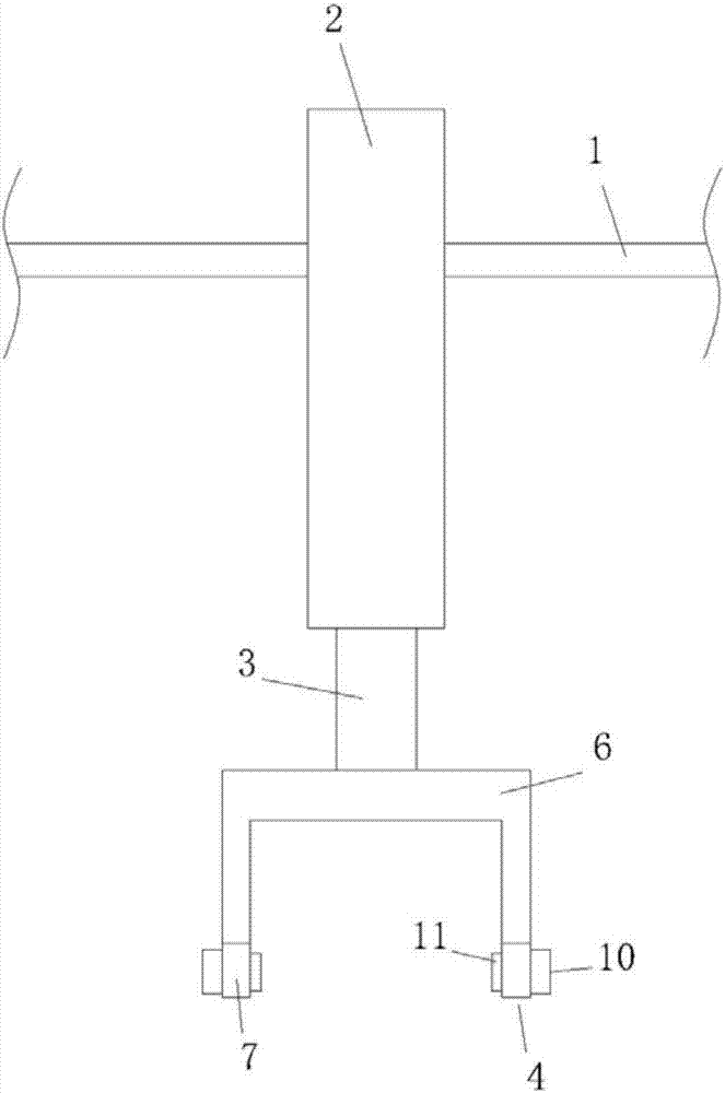
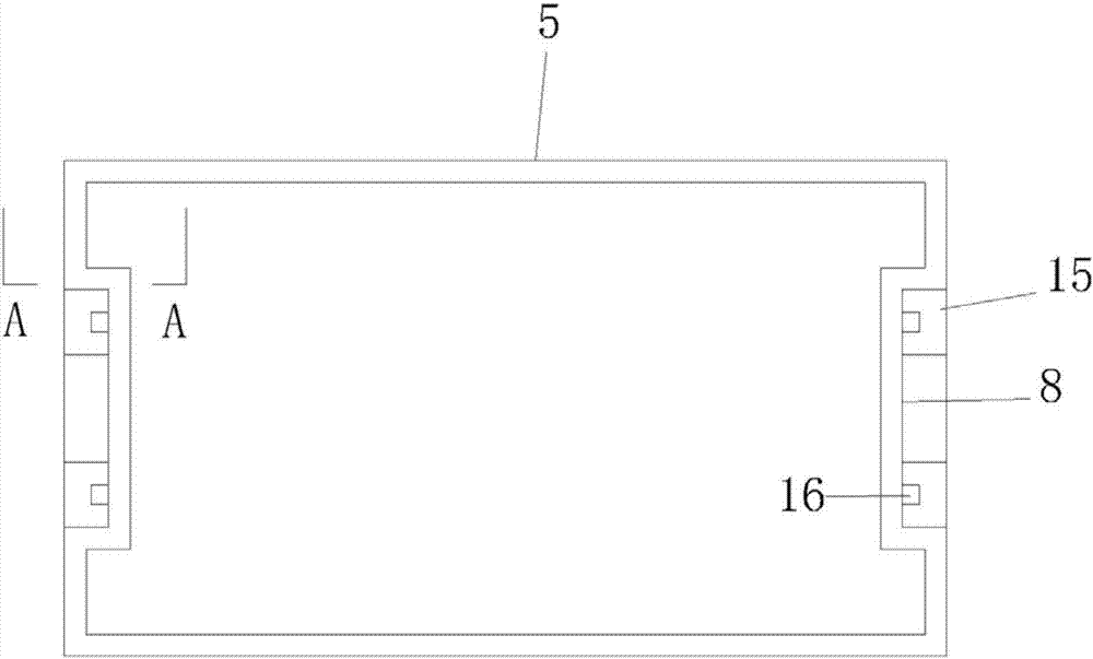
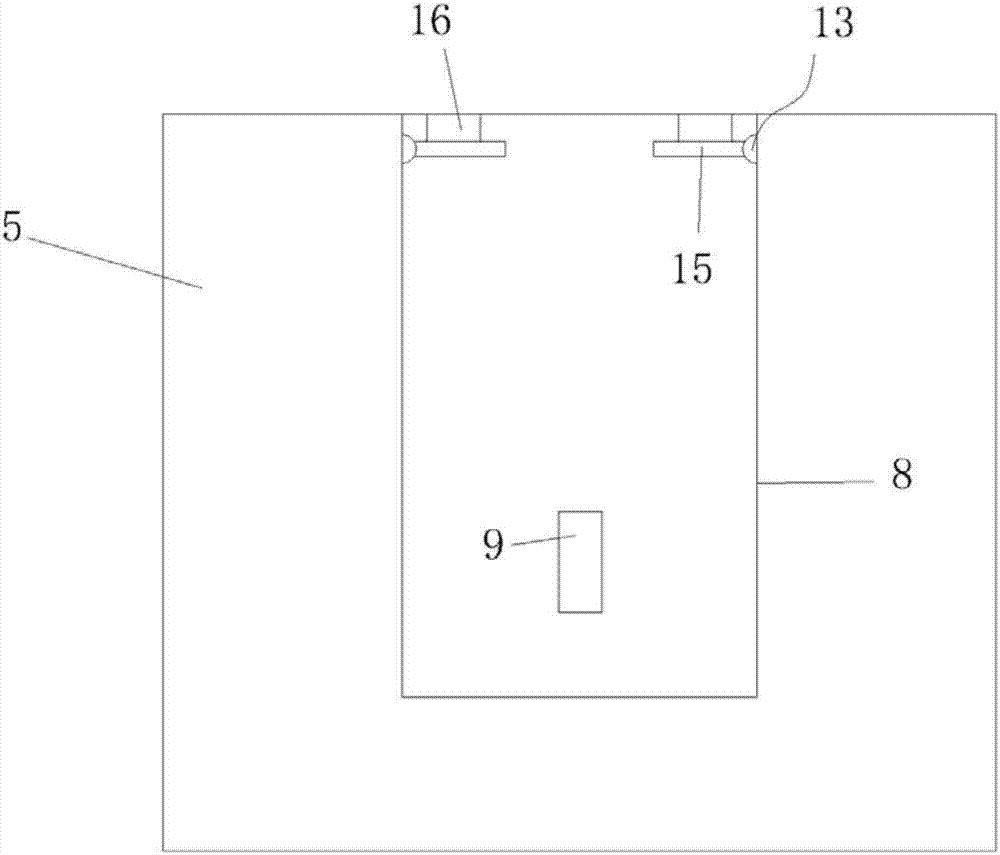
[0015] The mechanical arm system with conveying function as shown in the figure is characterized in that it comprises a slide rail 1 which is arranged transversely, a sliding end 2 which is matched with the slide rail 1, a lifting part 3 which is telescopically arranged in the sliding end 2 , The grabbing portion 4 provided at the end of the lifting portion 3 and the storage box 5 for the grabbing portion 4 to grab, the bottom of the lifting portion 3 is provided with an extension rod 6 with a corner, and the grabbing portion 4 is provided at the end of the extension rod 6, And the grabbing part 4 is provided with a retractable grabbing device for grabbing the storage box 5.
[0016] When in use, slide the sliding end 2 horizontally to a suitable position to lower the lifting part 3 so that the grabbing part 4 can grab the storage box 5. When the grabbing device grabs the storage box 5, the lifting part 3 shrinks upwards and slides Inside the end 2 and sliding with the sliding end 2 to transport the storage box 5. It is worth noting that the sliding of the lifting part 3 in the sliding end 2 and the sliding of the sliding end 2 on the sliding rail 1 both adopt the existing technology. At the same time, the grasping device can also adopt the existing technology, such as a vacuum suction cup, or directly apply a clamping force to the storage box 5 to clamp it.
[0017] The extension rod 6 extends to both sides and extends downward, and its turning can be a corner or an arc, depending on the shape of the storage box 5.
[0018] Preferably, the grasping device includes an insertion plate 7 provided at the end of the extension rod 6 and a power unit and an action unit respectively provided on both sides of the insertion plate 7. The power unit provides power to make the action unit expand and contract, and the storage box 5 is provided on both sides The slot 8 is provided with a square jack 9 for inserting the power unit. In order to better grasp the glove box 5, slots 8 are provided on both sides of the glove box 5, the insertion plate 7 of the grasping device is inserted into the slot 8, and the power unit provides power to push the action unit to slide. The power unit can be an electric motor or a hydraulic device. It should be noted that the shape of the jack 9 is square, and the corresponding action unit inserted into the jack 9 is also square.
[0019] Preferably, the power unit is a linear motor 10, and the power unit is a limit pin 11 that is dynamically connected to the linear motor 10. The limit pin 11 is arranged to slide under the push of the linear motor 10 to extend from the insertion plate 7 into the insertion hole Within 9. The linear motor 10 and the limit inserting rod 11 are connected by a conventional transmission, so that the limit inserting rod 11 is telescopic and sliding on the inserting plate 7.
[0020] Preferably, both sides of the top end of the slot 8 are provided with accommodating grooves 12 in which a rotating shaft 13 is provided. A sleeve 14 is provided on the rotating shaft 13 coaxially, and the sleeve 14 is connected with the baffle plate 15. The spring 17 is connected to the inner wall of the accommodating groove 12, and the two sides of the inner wall of the slot 8 are fixed with limit blocks 16 that restrict the upward rotation of the baffle 15. 7 is provided with a through groove 18 slidingly fitted with the limiting block 16 on the inner side. When the insertion plate 7 is inserted into the slot 8, the baffle 15 is pushed to move downward, and the opening is opened to allow the insertion plate 7 to enter. At the same time, the through slot 18 opened by the insertion plate 7 prevents it from being caught by the limit block 16. The insertion plate 7 is reset under the action of the torsion spring 17, the baffle 15 just touches the lifting part 3 after reset, and at the same time, the baffle 15 cannot continue to rotate due to the existence of the stop block 16. Even if the limit inserting rod 11 is not inserted into the socket 9 due to a mechanical failure, the inserting plate 7 can grab the storage box 5 and lift it for transportation under the restriction of the baffle 15.

PUM

no PUM

Description & Claims & Application Information

We can also present the details of the Description, Claims and Application information to help users get a comprehensive understanding of the technical details of the patent, such as background art, summary of invention, brief description of drawings, description of embodiments, and other original content. On the other hand, users can also determine the specific scope of protection of the technology through the list of claims; as well as understand the changes in the life cycle of the technology with the presentation of the patent timeline. Login to view more.

Similar technology patents

Nut mounting manipulator and nut mounting system

PendingCN108723741Aeasy to grabIncrease productivity
Owner:成都毓恬冠佳汽车零部件有限公司

Raw material frame rotating position-changing mechanism of condenser elastic screw cap installing machine

InactiveCN104722979Aeasy to grab
Owner:苏州市吴中区木渎华利模具加工店

Elastic nut kicking mechanism of condenser elastic nut installing machine

InactiveCN104741898Aeasy to grab
Owner:苏州市吴中区木渎华利模具加工店

Automatic loading and unloading truss for bending machine

PendingCN111604433Aeasy to grabGood practicality
Owner:LUOYANG YOUNENG AUTOMATION EQUIP CO LTD

Classification and recommendation of technical efficacy words

  • easy to grab

Flange separation mechanism and flange machining line with same

InactiveCN108438866AAvoid accumulation of flange partseasy to grab
Owner:ZHUHAI GREE INTELLIGENT EQUIP CO LTD +1

Automatic taking mechanism for mold products

InactiveCN110976821Aeasy to grabmobile stability
Owner:吴明博

Pressurized water reactor nuclear power plant reactor core checking tool

PendingCN110942836Aeasy to grabimprove security
Owner:CNNC FUJIAN FUQING NUCLEAR POWER

High-efficiency laser cutting and drilling device for hardware

ActiveCN111604601AEasy to grabGuaranteed accuracy
Owner:深圳市柯宝原科技有限公司

Medicine plate positioning, distributing and conveying device

PendingCN108163448Aeasy to grab
Owner:北京大森包装机械有限公司
Why Eureka
Try Eureka