Hinge structure

A hinge structure and hinge technology, applied in the field of hinges, can solve the problems of rusting of springs, affecting the normal use of hinges, disappearance or reduction of self-recovery force, etc., achieving the effects of convenient production and manufacturing, novel structural design and strong practicability

Pending Publication Date: 2017-12-01
CHANGHONG MEILING CO LTD
View PDF7 Cites 0 Cited by
  • Summary
  • Abstract
  • Description
  • Claims
  • Application Information

AI Technical Summary

Problems solved by technology

Because the spring has the risk of rust, it is easy to lose or reduce the self-recovery force due to the rust or fatigue of the spring during long-term use, which will affect the normal use of the hinge

Method used


Image

  • Hinge structure
  • Hinge structure
  • Hinge structure

Examples


Embodiment Construction

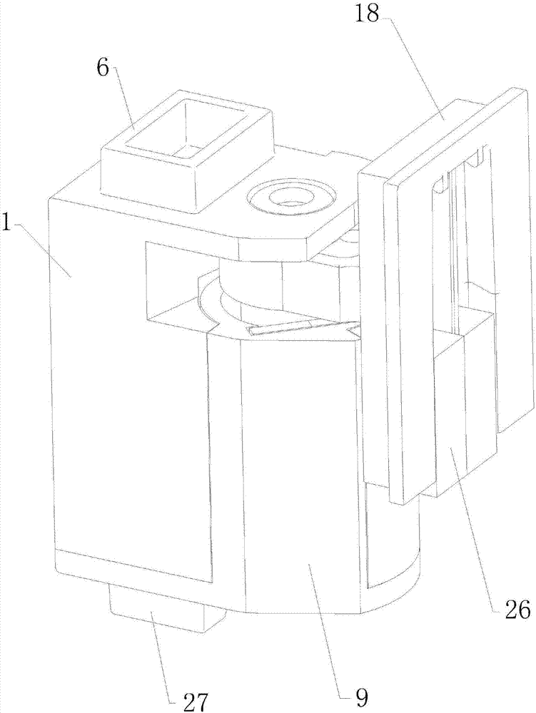
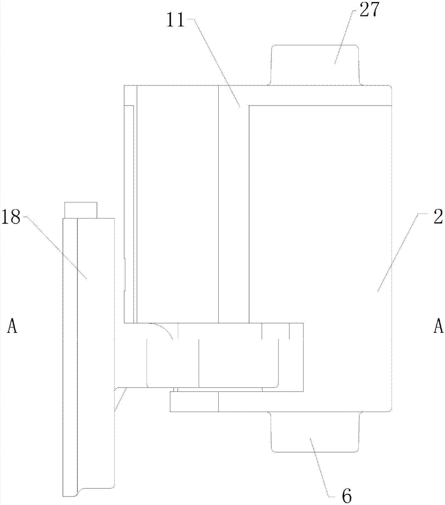
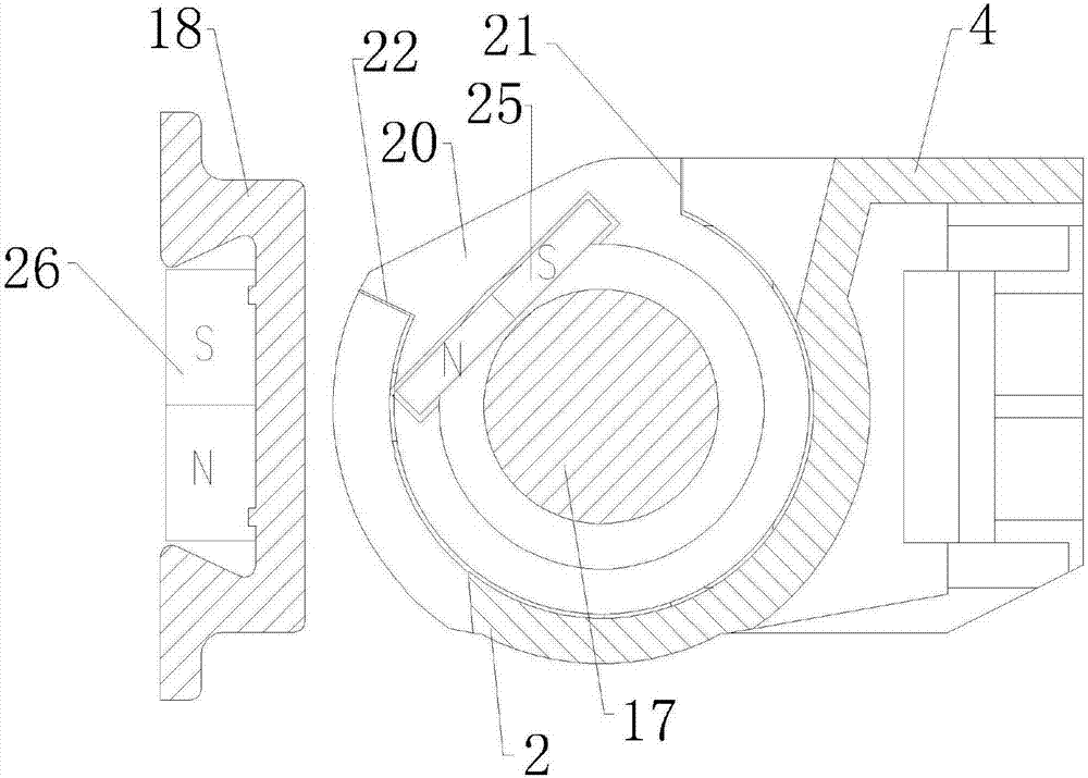
[0025] see Figure 1 to Figure 3 , the hinge structure of the present embodiment is to set a hinge box with a shaft hole inside, one side of the hinge 16 is arranged in the shaft hole with its columnar body 17 rotating and uses the columnar body 17 as the rotating shaft of the hinge 16, and the other side is The connecting plate 18 hanging outside the hinge box is provided with a magnet A 25 and a magnet B 26 respectively in the hinge box body and on the connecting plate 18. The magnetic pole directions of the magnet A 25 and the magnet B 26 are consistent and both rotate along the hinge 16. The tangential direction of the magnet A 25 and the magnet B 26 interact to provide a torque to rotate the hinge 16 .

[0026] Wherein, the hinge box is composed of a hinge box cover 1 and a hinge box seat 9 connected to each other, specifically:

[0027] see Figure 5 to Figure 7 , the hinge box cover 1 is provided with a tubular sleeve 2, which has a through hole 3 inside, and the thro...


PUM


Abstract

The invention provides a hinge structure. The hinge structure is provided with a hinge box with the inside being provided with a shaft hole. One side of a hinge is arranged in the shaft hole in a rotating mode through a cylindrical body, and the cylindrical body is used as a rotating shaft of the hinge. The other side of the hinge is provided with a connecting plate overhung at the outer side of the hinge box. A magnet A and a magnet B are arranged in a box body of the hinge box and the connecting plate correspondingly. The magnetic pole direction of the magnet A and the magnetic pole direction of the magnet B are consistent, and the magnet A and the magnet B are both arranged in the rotation tangential direction of the hinge. Under the interaction of the magnet A and the magnet B, twisting force for rotating the hinge can be provided. According to the hinge structure, the hinge self-resetting twisting force is provided under the magnetic interaction, and the product reliability is improved.

Description

technical field [0001] The invention relates to the technical field of hinges, more specifically to a hinge structure. Background technique [0002] Most of the hinges currently on the market with self-recovering force are realized by springs, and some are realized by using torsion springs or compression springs in conjunction with cam structures. Since the spring has the risk of rusting, it is easy to lose or reduce the self-recovering force due to the rust or fatigue of the spring during long-term use, which affects the normal use of the hinge. Contents of the invention [0003] In order to avoid the above-mentioned shortcomings of the prior art, the present invention provides a hinge structure, which provides hinge self-recovering torque through magnetic force interaction, and improves product reliability. [0004] To achieve the above object, the present invention adopts the following technical solutions: [0005] A hinge structure, which is provided with a hinge box...

Claims


Application Information

Patent Timeline
Patent Type & Authority Applications(China)
IPC IPC(8): E05D3/02E05F1/00E05F3/20
CPCE05D3/02E05F1/00E05F3/20
Inventor 田亚明李乾坤鲍敏
Owner CHANGHONG MEILING CO LTD
Why Eureka
Try Eureka