optical module

An optical module and optical sub-module technology, applied in the field of optical communication, can solve problems such as low heat conduction efficiency, and achieve the effects of improved heat conduction efficiency, good heat dissipation effect, and improved structure

Active Publication Date: 2019-06-04
广东海信宽带科技有限公司
View PDF2 Cites 0 Cited by
  • Summary
  • Abstract
  • Description
  • Claims
  • Application Information

AI Technical Summary

Problems solved by technology

[0005] An embodiment of the present invention provides an optical module, which is used to solve the problem of low heat conduction efficiency of existing optical modules

Method used


Image

  • optical module
  • optical module
  • optical module

Examples


Embodiment Construction

[0028] The following will clearly and completely describe the technical solutions in the embodiments of the present invention with reference to the accompanying drawings in the embodiments of the present invention. Obviously, the described embodiments are only some, not all, embodiments of the present invention. Based on the embodiments of the present invention, all other embodiments obtained by persons of ordinary skill in the art without making creative efforts belong to the protection scope of the present invention.

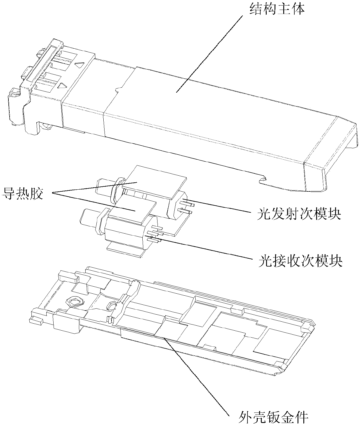
[0029] figure 1 It is a schematic diagram of the decomposition of the optical module in the prior art, such as figure 1 As shown, the upper surface of the structural main body of the existing optical module is a closed structure, and the shell sheet metal part of the lower surface of the structural main body of the optical module is also a closed structure. The surface of the optical module in the optical module is a curved surface. Thermal conductive glue is...


PUM


Abstract

The present disclosure provides an optical module, including: an optical sub-module (1) and a first housing (2); where a first sub-surface of the optical sub-module is provided with a first boss (11), and the first housing is provided with a first opening (21) corresponding to the first boss. The improved structure of the optical module can greatly increase heat conduction efficiency of the optical module.

Description

technical field [0001] The invention relates to optical communication technology, in particular to an optical module. Background technique [0002] The optical module is mainly used for photoelectric conversion. The transmitting end of the optical module converts the electrical signal into an optical signal and transmits it through the optical fiber. The receiving end of the optical module converts the received optical signal into an electrical signal. During the photoelectric conversion process, the optical module will continuously generate heat. The heat generated by the optical module needs to be dissipated in time. If the heat generated by the optical module is not dissipated in time, it will affect the normal operation of the optical module. [0003] The component that generates the most heat in the optical module is the Transmitting Optical Sub-Assembly (TOSA for short). In the prior art, the heat dissipation method of the optical module is mainly as follows: setting ...

Claims


Application Information

Patent Timeline
Patent Type & Authority Patents(China)
IPC IPC(8): H05K7/20H04B10/27
CPCH04B10/27H05K7/2039G02B6/4269G02B6/387G02B6/4246G02B6/4256H04B10/40H04B10/50H04B10/60
Inventor 陈彪杨柳荫
Owner 广东海信宽带科技有限公司
Why Eureka
Try Eureka