Nozzle tip of pulverized coal burner

A pulverized coal burner, nozzle head technology, applied in the direction of burner, burner burning powder fuel, combustion method, etc., can solve the problems that the nozzle head cannot perform the specific function of the nozzle head, the shared rod falls off, cracks, etc., and achieves improvement Abrasion phenomenon and detachment phenomenon, replacement cost saving, and effect of increasing wear resistance

Inactive Publication Date: 2017-12-01
DOOSAN HEAVY IND & CONSTR CO LTD
View PDF9 Cites 4 Cited by
  • Summary
  • Abstract
  • Description
  • Claims
  • Application Information

AI Technical Summary

Problems solved by technology

[0013] However, if image 3 As shown, there is a problem that one side of the sharing rod 60 collides head-on with the pulverized coal flowing through the guide vane 50, thereby causing partial or whole wear.
[0014] In addition, there is a problem in that the nozzle head 20 is exposed to high radiant heat inside the combustion chamber, which generates cracks in the welded portion of the sharing rod 60, causing the sharing rod to come off.
[0015] As mentioned above, if the sharing rods wear or fall off, the nozzle head can no longer perform the specific function as a nozzle head. The function of pulling the flame towards the side of the nozzle head, thus, problems arise in regulating the flame temperature and ensuring nitrogen oxides (NOx)

Method used


Image

  • Nozzle tip of pulverized coal burner
  • Nozzle tip of pulverized coal burner
  • Nozzle tip of pulverized coal burner

Examples


Embodiment Construction

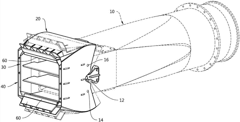
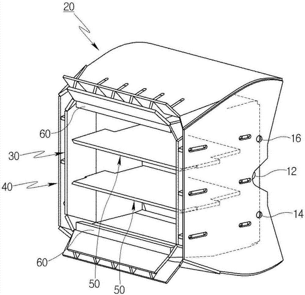
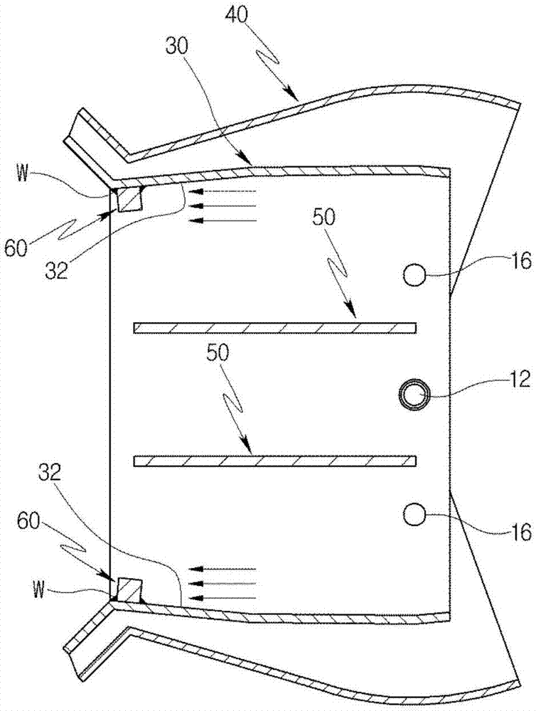
[0045] Below, refer to the attached Figure 4 to Figure 11 A preferred embodiment of the nozzle tip of the pulverized coal burner of the present invention will be described.

[0046] In addition, the terms described later are terms defined in consideration of the functions in the present invention, which can be changed according to the user's, operator's intention or custom, and the following examples do not limit the claims of the present invention, but merely Examples of constituent elements set forth in the claims of the present invention.

[0047] In order to clearly describe the present invention, parts irrelevant to the description are omitted, and the same reference numerals are attached to the same or similar constituent elements throughout the specification. Throughout the specification, when it is mentioned that certain components "include" certain components, unless there is a specific statement to the contrary, it does not mean that other components are excluded, ...


PUM


Abstract

The present invention relates to a nozzle tip of a pulverized coal burner, capable of solving an abrasion phenomenon and a deviation phenomenon of a flame stabilizer due to flow of pulverized coal. The nozzle tip of a pulverized coal burner comprises: an inner tube body having a first passage through which pulverized coal is introduced and moved; an outer tube body installed to be spaced apart from the inner tube body on the outside of the inner tube body; one or more guide plates installed to divide the first passage; and a plurality of flame stabilizers arranged on upper and lower sides of the inside of the inner tube body in series. In the flame stabilizers, a side facing a direction in which pulverized coal flows through the first passage is formed as an inclined surface inclined toward a center of the inner tube body.

Description

technical field [0001] The present invention relates to a nozzle tip of a pulverized coal burner, in particular to a nozzle tip of a pulverized coal burner, the nozzle tip of the pulverized coal burner can improve the The wear phenomenon and detachment phenomenon of the flame stabilizer. Background technique [0002] Generally, in a boiler adopting a tangential combustion method, the nozzle head of the coal burner is arranged on the edge of the interior of the combustion chamber. [0003] In addition, the nozzle tip of the coal burner can change direction when starting the boiler. For example, the change of the up and down direction of the nozzle head can adjust the flame temperature inside the combustion chamber, and it can also be changed from the center of the combustion chamber to the clockwise or counterclockwise direction of the flame, so that the direction in which the coal as fuel is supplied Change. [0004] refer to Figure 1 to Figure 3 The configuration of a c...

Claims


Application Information

Patent Timeline
Patent Type & Authority Applications(China)
IPC IPC(8): F23D1/00
CPCF23D1/00F23D2201/10F23D2201/20F23D2201/30
Inventor 吴暻泽李炳和
Owner DOOSAN HEAVY IND & CONSTR CO LTD
Why Eureka
Try Eureka