
Clamping device with ratchet device for ground wire

A technology of clamping device and ratchet device, which is applied in the direction of electrical connection seat, connection contact material, overhead line/cable equipment, etc., and can solve the problems of inconvenient use, inability to use, inconvenient operation, etc.

Inactive Publication Date: 2017-12-01
JIANGMEN POWER SUPPLY BUREAU OF GUANGDONG POWER GRID
View PDF7 Cites 3 Cited by
  • Summary
  • Abstract
  • Description
  • Claims
  • Application Information

AI Technical Summary

Problems solved by technology

At present, during the grounding process of the power supply system, the staff need to perform screw tightening or loosening operations while wearing insulating gloves.
In addition, because the direction of the wire end of the grounding wire and the insulating rod is fixed, if it encounters a switchgear with vertically arranged busbars, the insulating rod of the grounding wire will be blocked by the busbar, making it impossible to use
[0003] In the prior art, there is already a clamping device in which the rod body and the connecting hole can be rotated relative to each other. However, when the insulating rod swings to lock the chuck or remove the chuck, the rod needs to be removed every time it swings. After adjusting the angle, the rod needs to be removed. Re-insert and continue to swing, need to go through many times of docking to realize the process of clamping or dismounting, which is inconvenient to operate and low in efficiency

Method used


Image

  • Clamping device with ratchet device for ground wire
  • Clamping device with ratchet device for ground wire
  • Clamping device with ratchet device for ground wire

Examples


Embodiment Construction

[0015] The accompanying drawings are for illustrative purposes only, and should not be construed as limitations on this patent; in order to better illustrate this embodiment, certain components in the accompanying drawings will be omitted, enlarged or reduced, and do not represent the size of the actual product; for those skilled in the art It is understandable that some well-known structures and descriptions thereof may be omitted in the drawings. The positional relationship described in the drawings is for illustrative purposes only, and should not be construed as a limitation on this patent.

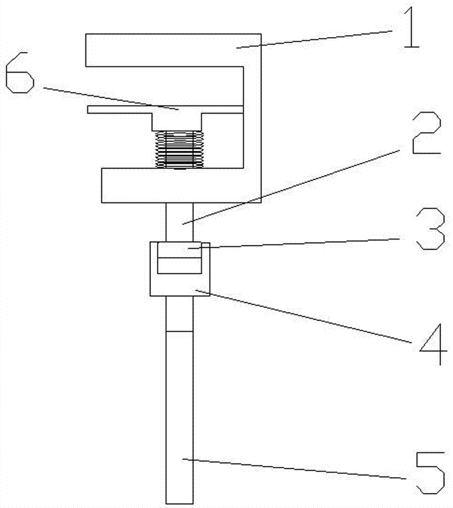
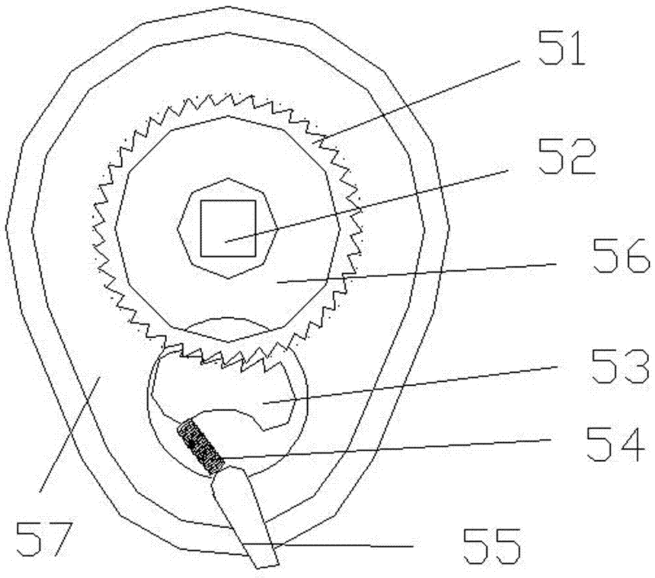
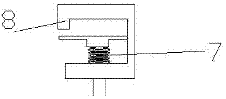
[0016] Such as Figure 1-3 As shown, a clamping device for a grounding wire with a ratchet device includes a chuck 1, a push column 2, a clip 6, a connecting frame 4, an insulating rod 5, and a ratchet fastening device 3. The clamp The head 1 includes an upper bump, a lower bump and a connecting block. The upper bump and the lower bump are arranged in parallel and respectively fixed ...


PUM


Abstract

The invention discloses a clamping device with a ratchet device for a ground wire. The clamping device comprises a chuck, a propelling post, a clamping piece, a connection frame, an insulating rod and a ratchet fastening device, wherein the chuck comprises an upper bump, a lower bump and a connection block; the upper bump and the lower bump are arranged in parallel and are fixed at two ends of the connection block separately to form a structure with a groove; the propelling post passes through the lower bump and is in threaded connection with the lower bump; the clamping piece is fixed at one end, entering the inside of the groove, of the propelling post; a fixture block is arranged at one end, outside the chuck, of the propelling post and is a polygon; the ratchet fastening device is hinged with the connection frame; the connection frame is fixedly connected with the insulating rod; the ratchet fastening device comprises a fixture block mating hole; and the fixture block mating hole is in fit connection with the fixture block. By adopting the ratchet device, the target that the propelling post can only rotate in the same hour hand direction and cannot rotate in the other hour hand direction in the swing process of the insulating rod can be achieved, so that the single tightening or disassembling process can be continuously achieved through only one-step installation.

Description

technical field [0001] The invention relates to the technical field of distribution network maintenance tools, and more particularly, to a clamping device for a grounding wire with a ratchet device. Background technique [0002] In the power outage maintenance work of the distribution network, it is necessary to ensure the safety of the staff through grounding. At present, during the grounding process of the power supply system, the staff need to perform screw tightening or loosening operations while wearing insulating gloves. In addition, because the direction of the wire end of the grounding wire and the insulating rod is fixed, if it encounters a switchgear with vertically arranged busbars, the insulating rod of the grounding wire will be blocked by the busbar, making it unusable. [0003] In the prior art, there is already a clamping device in which the rod body and the connecting hole can be rotated relative to each other. However, when the insulating rod swings to loc...

Claims


Application Information

Patent Timeline
IPC IPC(8): H01R11/26H01R4/66H02G1/02
CPCH01R11/26H01R4/66H02G1/02
Inventor 梁恩诚邝朝炼罗益荣胡小伦陈振中杨玺陈小慧
Owner JIANGMEN POWER SUPPLY BUREAU OF GUANGDONG POWER GRID
Learn More