winding spindle

A spindle and winding machine technology, applied in the direction of thin material processing, conveying filamentous materials, transportation and packaging, etc., can solve the problems of increasing the strength of the drive shaft, achieve strength improvement, avoid high notch stress, and increase design strength Effect

Active Publication Date: 2019-12-10
OERLIKON TEXTILE GMBH & CO KG
View PDF7 Cites 0 Cited by
  • Summary
  • Abstract
  • Description
  • Claims
  • Application Information

AI Technical Summary

Problems solved by technology

It is true that higher load capacity can be obtained through roller be

Method used


Image

  • winding spindle
  • winding spindle
  • winding spindle

Examples


Embodiment Construction

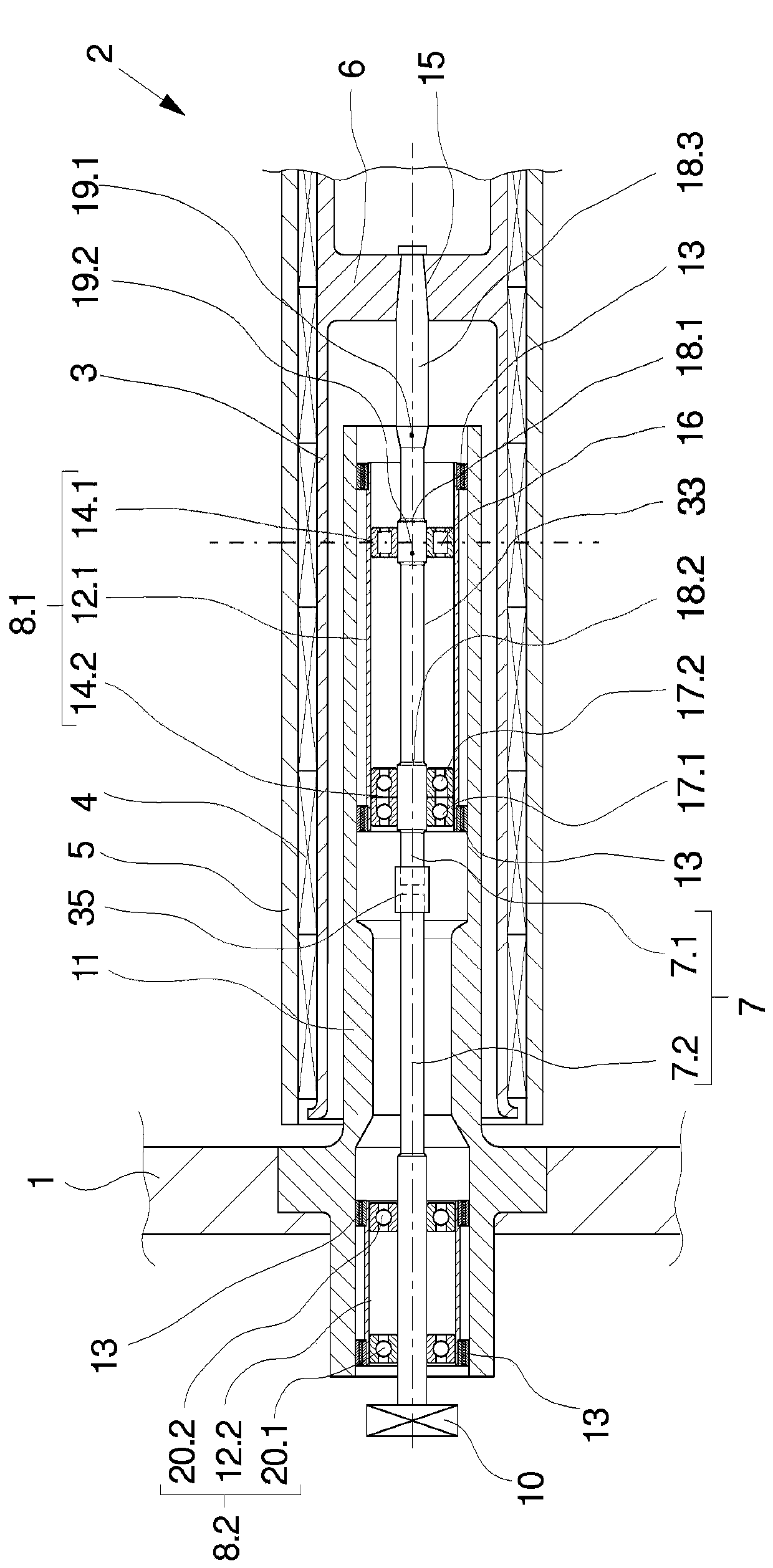
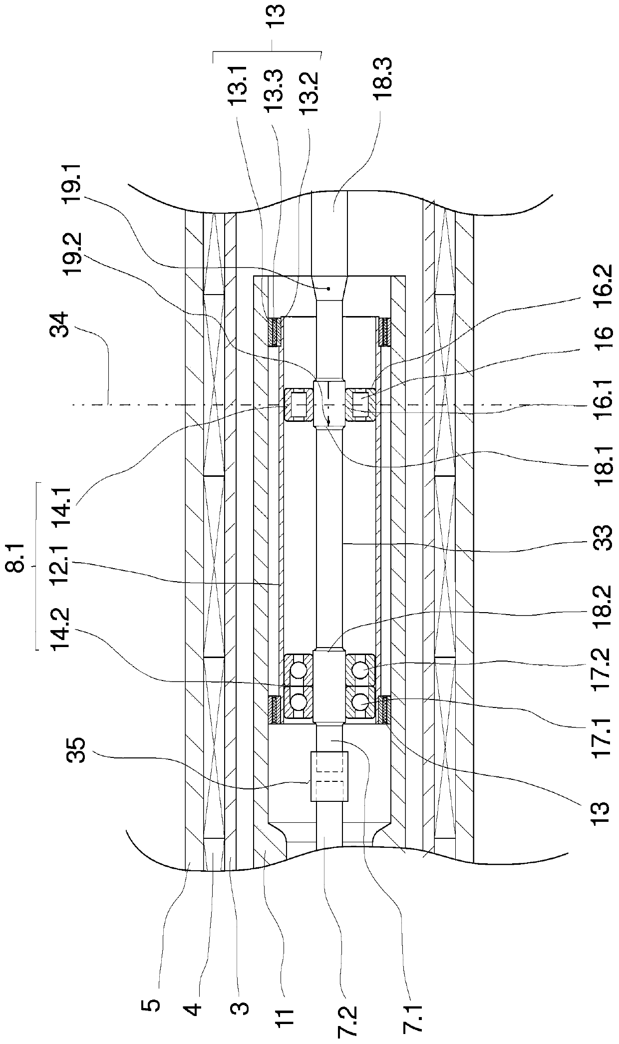
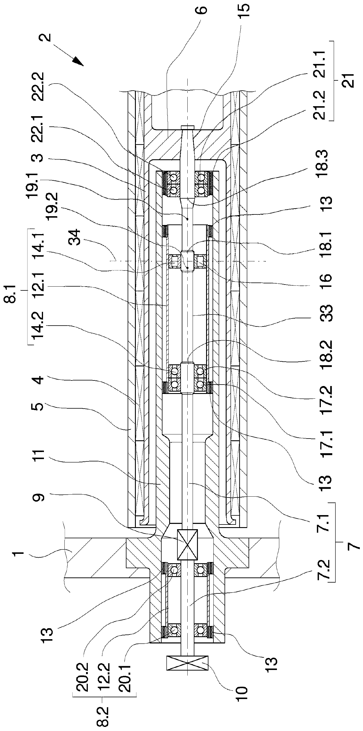
[0031] in figure 1 A cross-sectional view of the first exemplary embodiment of the winding spindle is illustrated in a partial view. The winding spindle 2 is held on the spindle support 1 by a hollow support 11. The winding spindle 2 on the spindle support 1 has a large number of protruding chucks 3, and the chucks 3 are configured to be hollow cylindrical at both ends. The free end of chuck 3 is figure 1 It is not shown in, this is because the free end does not include any components related to the present invention. The free end of the chuck 3 is usually closed by a cover.

[0032] The relatively open end of the chuck 3 facing the spindle support 2 is used to receive the drive shaft 7, and the drive shaft 7 is connected to the hub 6 of the chuck 3 through a shaft-hub connection 15.

[0033] Due to production technology, the drive shaft 7 is divided into two shaft parts and formed by a front bearing shaft 7.1 and a rear bearing shaft 7.2. The two bearing shafts 7.1 and 7.2 are ...


PUM


Abstract

The invention relates to a winding spindle for winding threads in a winding machine. For this purpose, the winding spindle has a long protruding chuck (3) for accommodating a plurality of winding tubes, wherein the chuck can be driven by means of a multi-part drive shaft (7) supported in a hollow support (11) and wherein a rear bearing shaft (7.2) is coupled to a drive. A front bearing shaft (7.1) coupled to the rear bearing shaft (7.2) is connected to the chuck (3) and supported in the hollow cylindrical hollow support (11) by means of a bearing unit. The bearing unit comprises a front rolling-element bearing (14.1) and a rear rolling-element bearing (14.2). According to the invention, in order to minimize the load on the bearing shaft caused by a rotary bending moment, the front rolling-element bearing (14.1) is arranged near a center of gravity (19.1) of the chuck (3) and bears nearly the entire weight of the chuck as a supporting bearing.

Description

Technical field [0001] The invention relates to a winding spindle for winding a wire into a plurality of bobbins in a winding machine. Background technique [0002] In the production of synthetic yarns in the melt spinning process, the yarns of one spinning station are collectively wound in parallel to form a bobbin. For this purpose, winding machines are used, each of which has a winding station for each thread and a winding spindle installed on one side parallel to the winding station. This type of winding spindle is arranged to protrude on the spindle support, so that the bobbin wound on the circumference of the winding spindle when completed can be removed from the free end of the winding spindle. For example, a winding spindle of this type is known from DE 195 48 142 A1. [0003] The known winding spindle has a chuck, and a clamping sleeve having a clamping device for receiving and fixing the winding tube is arranged on the circumference of the chuck. The chuck is implement...

Claims


Application Information

Patent Timeline
IPC IPC(8): B65H54/547
CPCB65H54/547B65H2701/31
Inventor H·瓦尔特曼K·谢弗
Owner OERLIKON TEXTILE GMBH & CO KG
Why Eureka
Try Eureka