
Spiral lift

A technology of a screw elevator and a lifting mechanism, applied in the field of lifting, can solve the problems of prolonging the construction delivery period, reducing the lifting weight, and reducing the lifting speed of the lifting weight, achieving reasonable structural design, solving space size, and high stability. Effect

Inactive Publication Date: 2017-12-05
WUHU C&K AUTOMATION TECH CO LTD
View PDF6 Cites 3 Cited by
  • Summary
  • Abstract
  • Description
  • Claims
  • Application Information

AI Technical Summary

Problems solved by technology

[0002] At present, the existing domestic lifting systems generally use traditional hydraulic cylinders, pneumatic cylinders, or screw methods to realize the process of lifting objects. During the rising process, the traditional lifting methods will gradually reduce the lifting weight according to the increase in height. Moreover, the height of the body becomes higher with the increase of the lifting height, which has great limitations.
It is impossible to find a lift that can meet such requirements in an environment where it is installed in a specific narrow space and the height of the body is not too high. Usually, the height can be raised, so the body of the lift must be correspondingly higher to realize its function, and it must drive the load. type objects, the lift body must be quite large and the lifting frame must be reinforced to meet the requirements. Some lifting systems have to dig deeper pits to put in large-volume lifts, which increases construction difficulty and prolongs construction delivery. If the method takes a long time, there will be oil leakage in the sealing part, and the maintenance frequency will be too much and troublesome; the current situation of lack of precision in the automatic control of the lifting, the screw lift makes the lifting weight and lifting speed significantly lower, and there is also a lot of lifting. The height of the high body needs to be raised and fixed.

Method used


Image

  • Spiral lift
  • Spiral lift
  • Spiral lift

Examples


Embodiment 1

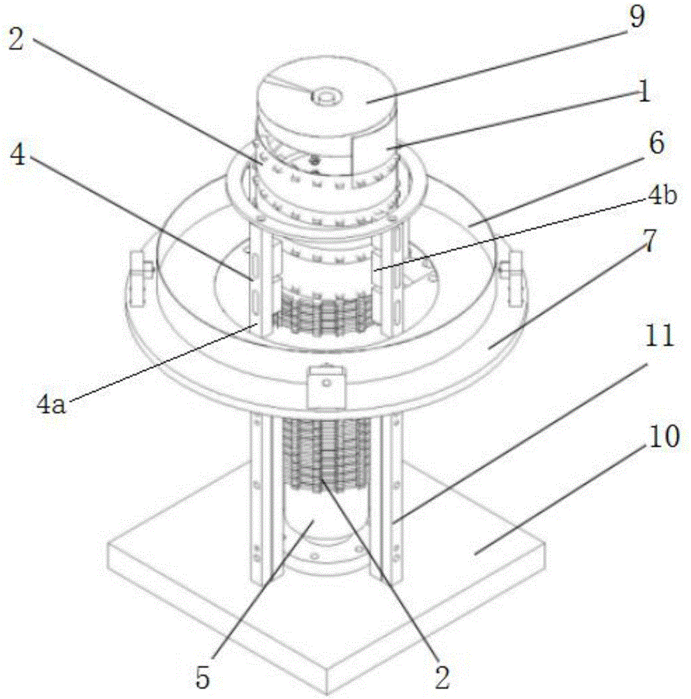
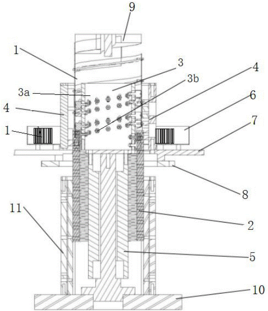
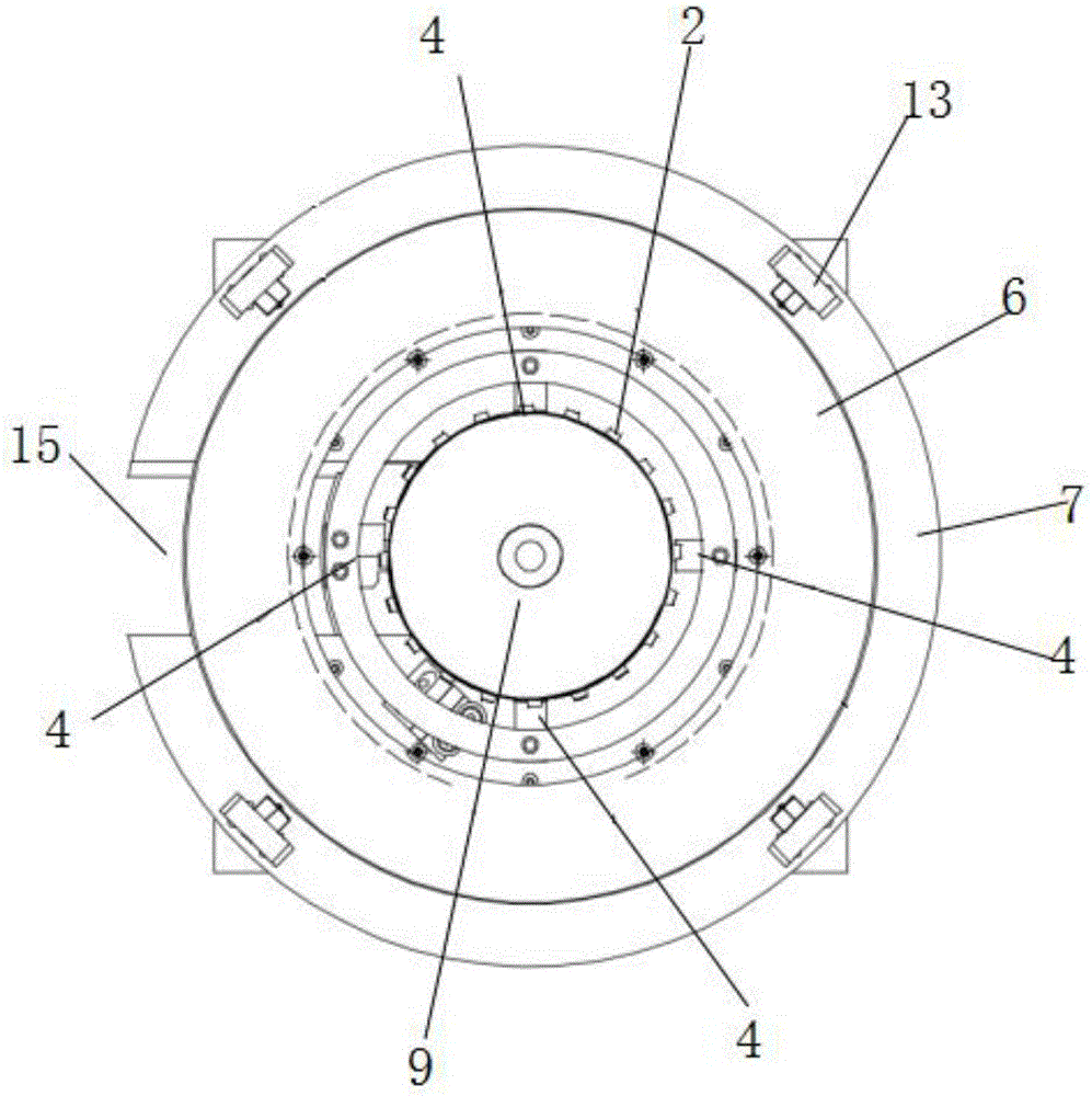
[0035] like Figure 1 to Figure 6 As shown, the screw jack includes a fixed base, a platform that rotates around the fixed base, a storage box 6 installed on the platform, a spring flat belt 1 stored in the storage box 6, installed in the fixed base and connected to the spring The flat belt 1 cooperates with the toothed spring bar 2 forming the spiral cylinder, and the belt track lifting mechanism installed on the platform is used to bind the toothed spring bar 2 to lift or shrink. The rail guide frame 4 that the bar 2 engages. External power drives the platform to rotate, and then drives the belt track lifting mechanism 3 to rotate, and the belt track lifting mechanism 3 makes the toothed spring bar 2 rise and fall under the guidance of the belt track lifting mechanism 3, and simultaneously pulls the spring flat belt 1 to spirally climb , Under the pushing action of the track guide frame 4, the spring flat belt 1 and the toothed spring bar 2 engage and form a spiral rising c...

Embodiment 2

[0051] like Figure 8 to Figure 11 As shown, the screw jack includes a fixed base, a platform that rotates around the fixed base, a storage box 6 installed on the platform, a spring flat belt 1 stored in the storage box 6, installed in the fixed base and connected to the spring The flat belt 1 cooperates with the toothed spring bar 2 forming the spiral cylinder, and the belt track lifting mechanism installed on the platform is used to bind the toothed spring bar 2 to lift or shrink. The rail guide frame 4 that the bar 2 engages. External power drives the platform to rotate, and then drives the belt track lifting mechanism 3 to rotate, and the belt track lifting mechanism 3 makes the toothed spring bar 2 rise and fall under the guidance of the belt track lifting mechanism 3, and simultaneously pulls the spring flat belt 1 to spirally climb , Under the pushing action of the track guide frame 4, the spring flat belt 1 and the toothed spring bar 2 engage and form a spiral rising ...


PUM


Abstract

The invention relates to a spiral lift. The spiral lift comprises a fixed base, a platform, a storage box, a flat spring belt, a toothed spring strip, a hoisting mechanism with a track and a track guiding frame, wherein the platform rotates around the fixed base; the storage box is installed on the platform; the flat spring belt is stored in the storage box; the toothed spring strip is installed in the fixed base and matched with the flat spring belt to form a spiral cylinder; the hoisting mechanism with the track is installed on the platform for constraining lifting movement or retracting movement of the toothed spring strip; and the track guiding frame is used for enabling the flat spring belt and the toothed spring strip to be engaged. The structure design is reasonable, the space is compact, the flat spring belt and the toothed spring strip are spirally engaged to form the spiral cylinder, so that rising and falling are achieved; the technical problem that a traditional lifting mechanism occupies large space is solved; and sudden decreasing of the hoisting force due to increasing of the hoisting height is avoided, and therefore stability is high.

Description

technical field [0001] The invention relates to the technical field of lifting, in particular to a screw jack. Background technique [0002] At present, the existing domestic lifting systems generally use traditional hydraulic cylinders, pneumatic cylinders, or screw methods to realize the process of lifting objects. During the rising process, the traditional lifting methods will gradually reduce the lifting weight according to the increase in height. Moreover, the height of the body becomes higher with the increase of the lifting height, which has great limitations. It is impossible to find a lift that can meet such requirements in an environment where it is installed in a specific narrow space and the height of the body cannot be too high. Usually, the height can be raised, so the body of the lift must be correspondingly higher to realize its function, and it must drive the load. type objects, the lift body must be quite large and the lifting frame must be reinforced to m...

Claims


Application Information

Patent Timeline
Patent Type & Authority Applications(China)
IPC IPC(8): B66F7/14B66F7/28B66F3/08
CPCB66F3/08B66F7/14B66F7/28B66F2700/04
Inventor 金虎杰
Owner WUHU C&K AUTOMATION TECH CO LTD
Learn More