Spiral direct jacking safety lifting elevator

A technology of safe lifting and screw lift, applied in lifts, elevators in buildings, transportation and packaging, etc., can solve the problems of high manufacturing cost, high screw processing accuracy, falling elevator car, etc., to make up for the lack of safety. , Reasonable structural design, the effect of simplifying the elevator structure

Inactive Publication Date: 2017-11-17
WUHU C&K AUTOMATION TECH CO LTD
View PDF6 Cites 6 Cited by
  • Summary
  • Abstract
  • Description
  • Claims
  • Application Information

AI Technical Summary

Problems solved by technology

However, this kind of elevator still has the phenomenon of car falling, and elevator failure or casualty accidents often occur in real life, which requires regular maintenance and inspection
[0004] The recently launched screw elevators are mostly based on the principle that the side screw connects the box body to rise and fall, but the traditional screw is noisy, the machining accuracy of the screw is high, the manufacturing cost is high, and the length of the screw needs to match the lifting height. Occupies a large space and cannot solve the problem of the car falling

Method used


Image

  • Spiral direct jacking safety lifting elevator
  • Spiral direct jacking safety lifting elevator
  • Spiral direct jacking safety lifting elevator

Examples


Embodiment 1

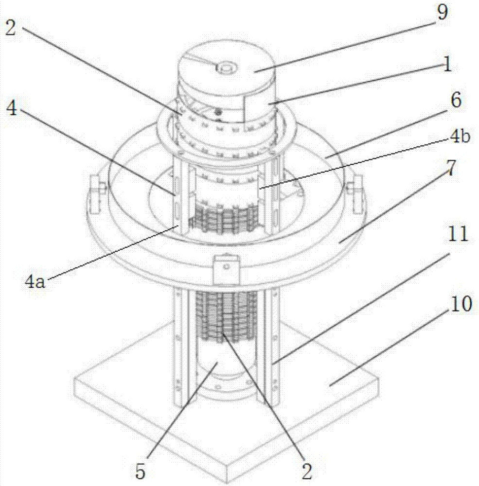
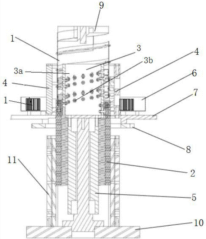
[0046] Such as Figure 2 to Figure 8 As shown, the screw jack 24 includes a fixed base, a platform that rotates around the fixed base, a storage box 6 installed on the platform, a spring flat belt 1 stored in the storage box 6, and is installed in the fixed base and Cooperate with the spring flat belt 1 to form the toothed spring bar 2 of the spiral cylinder, the belt track lifting mechanism installed on the platform for binding the toothed spring bar 2 to lift or shrink the movement 3, used to make the spring flat belt 1 and the tooth The track guide frame 4 that type spring bar 2 interlocks. External power drives the platform to rotate, and then drives the belt track lifting mechanism 3 to rotate, and the belt track lifting mechanism 3 makes the toothed spring bar 2 rise and fall under the guidance of the belt track lifting mechanism 3, and simultaneously pulls the spring flat belt 1 to spirally climb , Under the pushing action of the track guide frame 4, the spring flat be...

Embodiment 2

[0063] Such as Figure 9 to Figure 12 As shown, the screw jack 24 includes a fixed base, a platform that rotates around the fixed base, a storage box 6 installed on the platform, a spring flat belt 1 stored in the storage box 6, and is installed in the fixed base and Cooperate with the spring flat belt 1 to form the toothed spring bar 2 of the spiral cylinder, the belt track lifting mechanism installed on the platform for binding the toothed spring bar 2 to lift or shrink the movement 3, used to make the spring flat belt 1 and the tooth The track guide frame 4 that type spring bar 2 interlocks. External power drives the platform to rotate, and then drives the belt track lifting mechanism 3 to rotate, and the belt track lifting mechanism 3 makes the toothed spring bar 2 rise and fall under the guidance of the belt track lifting mechanism 3, and simultaneously pulls the spring flat belt 1 to spirally climb , Under the pushing action of the track guide frame 4, the spring flat b...


PUM


Abstract

The invention relates to a spiral direct jacking safety lifting elevator. The spiral direct jacking safety lifting elevator comprises an elevator support guide rail frame, and an elevator car sliding up and down along the elevator support guide rail frame; an elevator shaft is surrounded by the elevator support guide rail frame; multiple limiting sensors are distributed on the elevator support guide rail frame in the height direction of the elevator support guide rail frame; and the bottom of the elevator car is connected with a spiral lifter for urging lifting of the elevator car and fixed on the bottom ground of the elevator shaft. The spiral direct jacking safety lifting elevator further comprises a controller for connecting with the limiting sensors to control operation of the spiral lifter. The spiral direct jacking safety lifting elevator is reasonable in structural design and compact in space, simplifies the elevator structure, adopts the spiral lifter to supply the lifting force from the bottom of the elevator car to effectively solve the elevator car falling problem, adopts a spring flat belt and a tooth-shaped spring bar to spirally engage to form a spiral cylinder to realize lifting, solves the technical difficulty of larger space size occupied by a traditional lifting mechanism, and is higher in stability.

Description

technical field [0001] The invention relates to the technical field of elevator lifting, in particular to a spiral straight top safety elevator. Background technique [0002] Elevators are widely used in people's lives, such as high-rise residences, shopping malls, etc., which bring great convenience to people's production and life. [0003] Modern elevators are mainly composed of traction machine winch, guide rail, counterweight device, safety device (such as speed limiter, safety gear and buffer, etc.), signal control system, car and hall door. These parts are respectively installed in the hoistway and machine room of the building. Steel wire rope friction transmission is usually used. The wire rope goes around the traction sheave, and the two ends are respectively connected to the car and the counterweight. The motor drives the traction sheave to lift the car up and down. But this kind of elevator still has the phenomenon that the car falls, and elevator failure or casu...

Claims


Application Information

Patent Timeline
Patent Type & Authority Applications(China)
IPC IPC(8): B66B7/02B66B11/02
CPCB66B7/023B66B11/0226
Inventor 金虎杰
Owner WUHU C&K AUTOMATION TECH CO LTD
Why Eureka
Try Eureka