Spiral lifting system for ship

A technology of screw lift and screw lift, applied in the field of ship screw lift system, can solve the problems of increasing the weight of the ship, increasing the occupied area and volume, and the size of the machine room, etc., and achieves small space size and reasonable structural design. , the effect of high safety performance

Pending Publication Date: 2018-02-13
WUHU C&K AUTOMATION TECH CO LTD
View PDF8 Cites 2 Cited by
  • Summary
  • Abstract
  • Description
  • Claims
  • Application Information

AI Technical Summary

Problems solved by technology

At present, the lifting deck system on the ship still uses the traction lifting method, resulting in a large space occupation and the need for a machine room and many other factors that cannot reduce the size
This increases the weight of the ship and increases the occupied area and volume.

Method used


Image

  • Spiral lifting system for ship
  • Spiral lifting system for ship
  • Spiral lifting system for ship

Examples


Embodiment 1

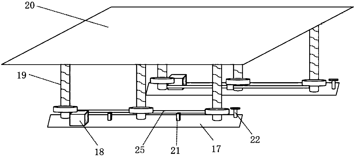
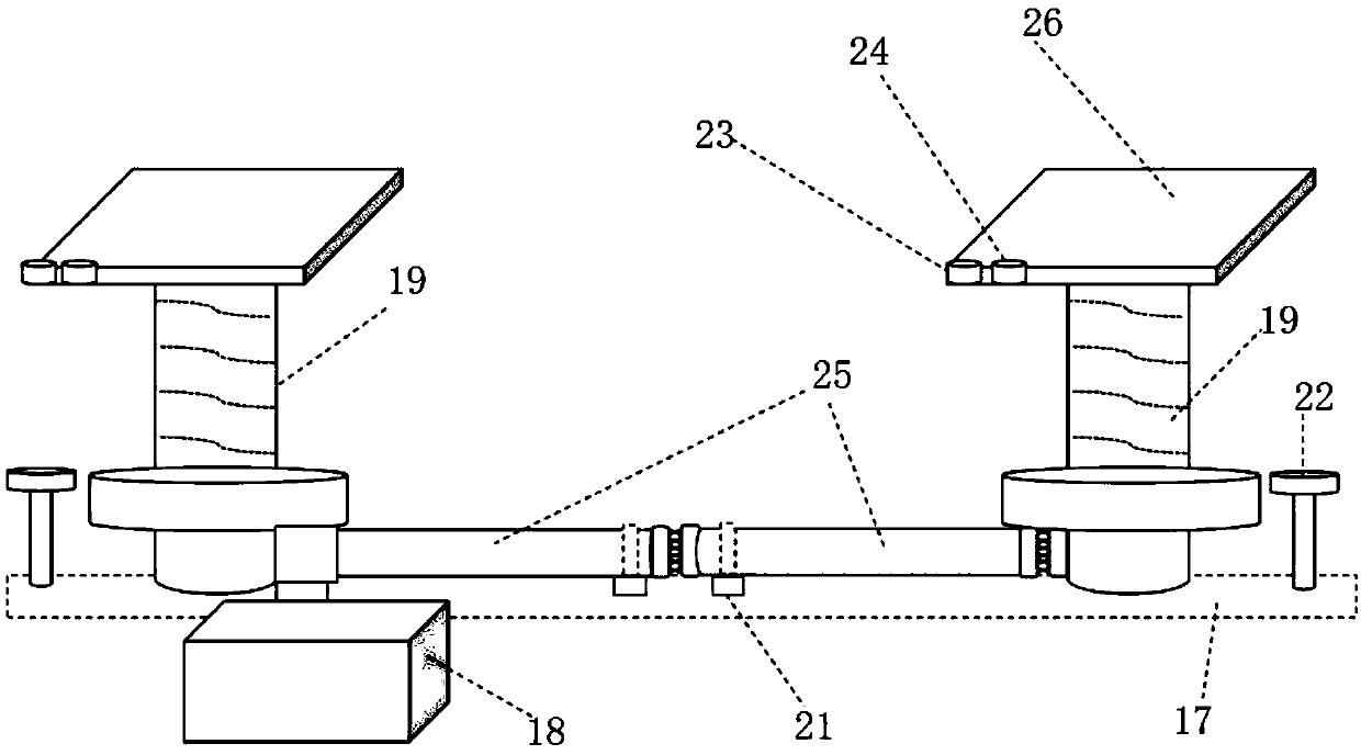
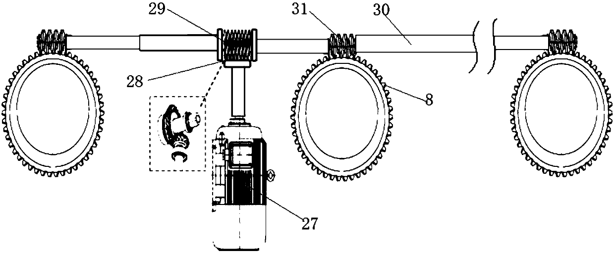
[0043] Such as Figure 4 to Figure 9 As shown, the screw jack 19 includes a fixed base, a platform that rotates around the fixed base, a storage box 6 installed on the platform, a spring flat belt 1 stored in the storage box 6, installed in the fixed base and Cooperate with the spring flat belt 1 to form the toothed spring bar 2 of the spiral cylinder, the belt track lifting mechanism installed on the platform for binding the toothed spring bar 2 to lift or shrink the movement 3, used to make the spring flat belt 1 and the tooth The track guide frame 4 that type spring bar 2 interlocks. The motor 27 drives the platform to rotate, and then drives the belt track lifting mechanism 3 to rotate, and the belt track lifting mechanism 3 makes the toothed spring bar 2 go up and down under the guidance of the belt track lifting mechanism 3, and simultaneously pulls the spring flat belt 1 to spirally climb , Under the pushing action of the track guide frame 4, the spring flat belt 1 and...

Embodiment 2

[0062] Such as Figure 10 to Figure 13 As shown, the screw jack 19 includes a fixed base, a platform that rotates around the fixed base, a storage box 6 installed on the platform, a spring flat belt 1 stored in the storage box 6, installed in the fixed base and Cooperate with the spring flat belt 1 to form the toothed spring bar 2 of the spiral cylinder, the belt track lifting mechanism installed on the platform for binding the toothed spring bar 2 to lift or shrink the movement 3, used to make the spring flat belt 1 and the tooth The track guide frame 4 that type spring bar 2 interlocks. The motor 27 drives the platform to rotate, and then drives the belt track lifting mechanism 3 to rotate, and the belt track lifting mechanism 3 makes the toothed spring bar 2 go up and down under the guidance of the belt track lifting mechanism 3, and simultaneously pulls the spring flat belt 1 to spirally climb , Under the pushing action of the track guide frame 4, the spring flat belt 1 a...


PUM


Abstract

The invention relates to a spiral lifting system for a ship. The spiral lifting system for the ship comprises a plurality of rows of spiral lifting devices, a controller and a deck platform, wherein the spiral lifting devices are fixed on a ship body; the controller is used for controlling operation of the spiral lifting devices; and the deck platform is mounted on the tops of the spiral lifting devices. Each spiral lifting device comprises a plurality of spiral elevators which are arranged along the ship body side by side, supporting blocks mounted on the tops of the spiral elevators and drivers, and each driver drives the corresponding row of spiral elevators to rotate. The spiral lifting system for the ship is reasonable in structural design; lifting movement of a deck is realized by aspiral lifting mode, the space is compact in structure, after the spiral lifting system for the ship retracts, the size of space occupied by the whole spiral lifting system is small, the technical problem that the traditional deck lifting mechanism occupies large space is solved, lifting force cannot be reduced suddenly along with increasing of lifting height, and the spiral lifting system for theship is high in stability and high in safety performance.

Description

technical field [0001] The invention relates to the technical field of ship deck lifting, in particular to a screw lifting system for ships. Background technique [0002] The deck is one of the important parts of the ship. The deck divides the ship into upper and lower parts. The part above the main deck is collectively called the superstructure; the part below the main deck is called the main hull. [0003] In the rapidly developing national defense field of our country, more and more naval warships are launched, and the ships tend to be more and more compact, stealthy, and modular. At present, the lifting deck system on ships still uses a traction lifting method, which leads to a large space occupation and the need for a machine room and many other factors that cannot be reduced in size. This increases the weight of the ship and increases the occupied area and occupied volume. Therefore urgently need a kind of new deck lifting system. Contents of the invention [0004...

Claims


Application Information

Patent Timeline
Patent Type & Authority Applications(China)
IPC IPC(8): B63B3/48
CPCB63B3/48B63B2003/485
Inventor 金虎杰
Owner WUHU C&K AUTOMATION TECH CO LTD
Why Eureka
Try Eureka