Tightness detection device and method suitable for straight-through stop valve

A technology of air tightness detection and stop valve, which is applied in measuring devices, uses liquid/vacuum degree for liquid tightness measurement, and detects the appearance of fluid at the leakage point, etc., can solve the design direction inconsistency and improve air tightness detection Cost, disassembly and assembly remain unchanged, to achieve the effect of easy operation and disassembly, ensuring application safety, and improving the detection range

Active Publication Date: 2017-12-05
HUBEI SANJIANG AEROSPACE HONGFENG CONTROL
View PDF7 Cites 11 Cited by
  • Summary
  • Abstract
  • Description
  • Claims
  • Application Information

AI Technical Summary

Problems solved by technology

However, there are certain defects or disadvantages in the above methods. For example, the detection method used in method 1 is not rigorous, and the test gas flow direction does not match the design direction of the stop valve, and does not meet the relevant regulations for the air tightness test of the stop valve; method On the one hand, the detection method used in the second method is complicated to operate, which is not conducive to the continued sale of the shut-off valve after the test, and on the other hand, it does not meet the requirements for the air tightness test of each shut-off valve; although the detection method adopted in the third method is in the above Many improvements have been made on the basis of the two methods, which can also solve the problem of air tightness detection of the globe valve to a certain extent, but its structure is complicated, and the disassembly and assembly are unchanged, which is not conducive to the air tightness test of the globe valve in batches.
The above-mentioned existing check valve air tightness detection method has greatly affected the accuracy of the check valve air tightness test, reduced the efficiency of the check valve air tightness test, and increased the cost of air tightness test

Method used


Image

  • Tightness detection device and method suitable for straight-through stop valve
  • Tightness detection device and method suitable for straight-through stop valve
  • Tightness detection device and method suitable for straight-through stop valve

Examples


Embodiment Construction

[0047] In order to make the object, technical solution and advantages of the present invention clearer, the present invention will be further described in detail below in conjunction with the accompanying drawings and embodiments. It should be understood that the specific embodiments described here are only used to explain the present invention, not to limit the present invention.

[0048] In addition, the technical features involved in the various embodiments of the present invention described below can be combined with each other as long as they do not constitute a conflict with each other.

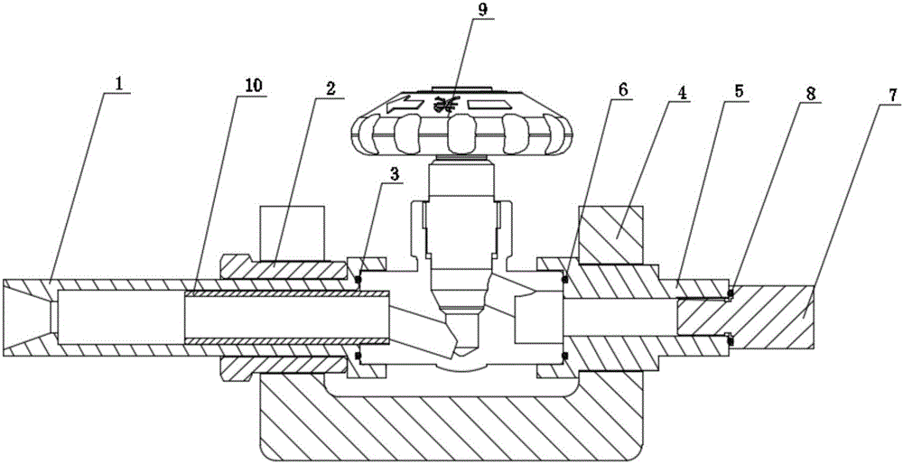
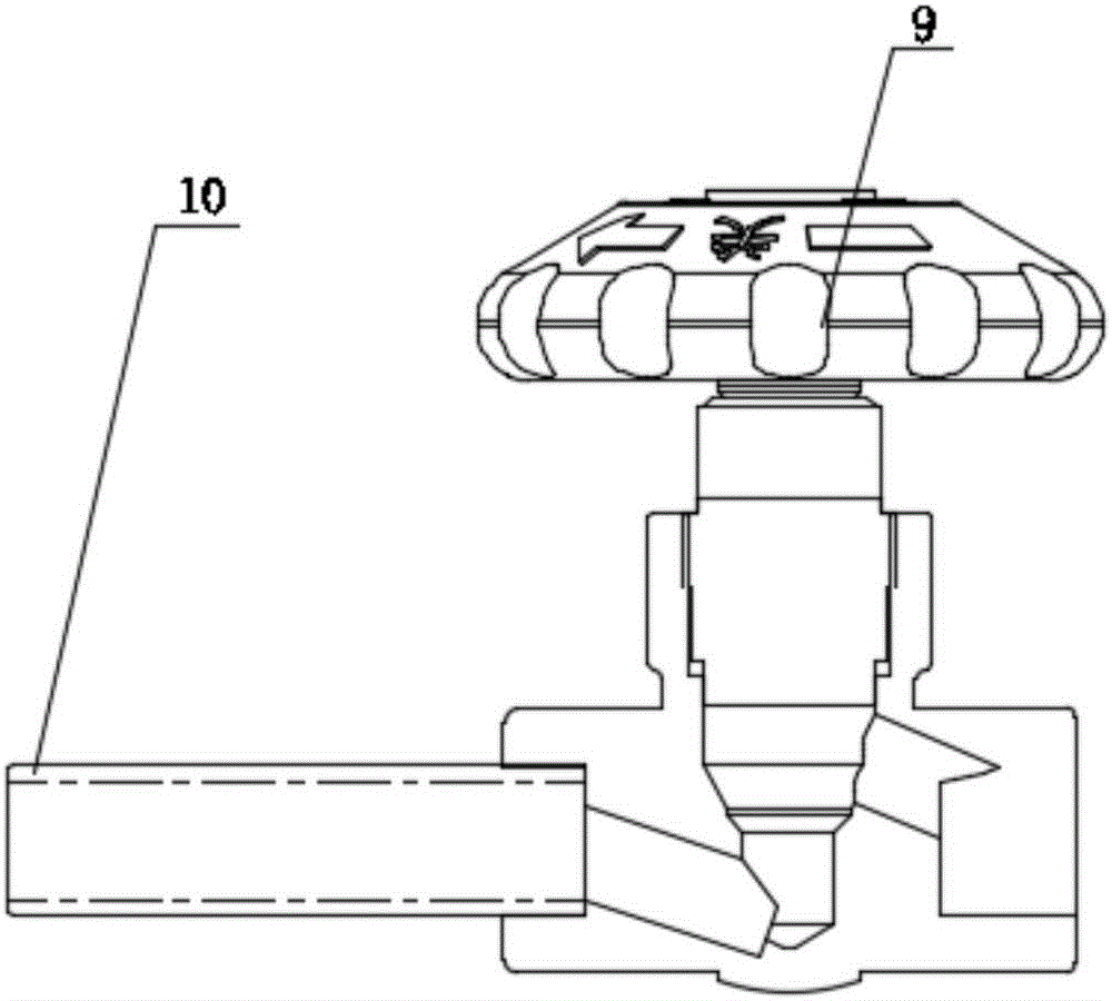
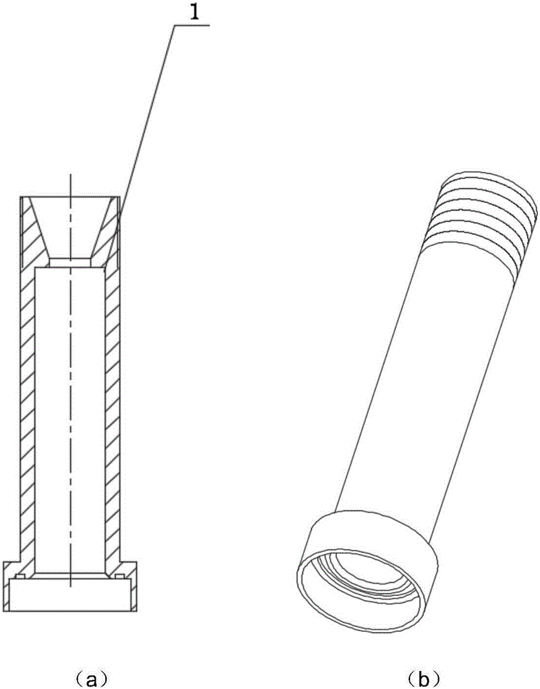
[0049] figure 1 It is a cross-sectional view of the overall structure of an air tightness detection device suitable for a straight-through globe valve according to an embodiment of the present invention; figure 2 It is a structural schematic diagram of a stop valve that uses the air tightness detection device of the embodiment of the present invention to detect the air tightness; Fi...


PUM


Abstract

The invention discloses a tightness detection device and method suitable for a straight-through stop valve and belongs to the valve detection technology field. The device comprises a first joint, a second joint, a support, a locking nut and a plug, wherein sealingness of an air inlet and an air outlet of the straight-through stop valve is realized through arranging O-shaped rings corresponding to the air inlet and the air outlet of the straight-through stop valve respectively for sealing on the first joint and the second joint, and external leakage and/or internal leakage detection on the straight-through stop valve is realized through in combination with dismounting and mounting of the plug and opening and closing of the valve. The device is advantaged in that not only can the structure be simple, the device is easy to dismount, tightness detection efficiency of the straight-through stop valve can be effectively improved, tightness detection accuracy of the straight-through stop valve can be effectively improved, use safety of the straight-through stop valve is guaranteed, moreover, and the device is quite suitable for tightness detection on the straight-through stop valve of which the air inlet is welded with an optical tube.

Description

technical field [0001] The invention belongs to the technical field of valve detection, and in particular relates to an air tightness detection device and a detection method suitable for straight-through stop valves. Background technique [0002] With the continuous development of liquefied natural gas (LNG) related technologies, the application range of LNG is becoming wider and wider, and the demand for stop valves matching it is also increasing, and the performance requirements for stop valves are also increasing. The stricter, and the air tightness test is a must-do test item in the performance testing process of the globe valve, which is directly related to the service life and safety of the globe valve. [0003] For different application environments, the stop valves used are also different. According to the difference in the flow direction of the stop valve channel, the commonly used stop valves can be divided into straight-through stop valves and angle-type stop valv...

Claims


Application Information

Patent Timeline
Patent Type & Authority Applications(China)
IPC IPC(8): G01M3/08G01M3/02
CPCG01M3/022G01M3/086
Inventor 张晶周华波赵磊王程勇叶飞
Owner HUBEI SANJIANG AEROSPACE HONGFENG CONTROL
Why Eureka
Try Eureka