Dispensing jig and dispensing equipment with the dispensing jig

A dispensing and fixture technology, which is applied to the device and coating of the surface coating liquid, which can solve the problem of overflowing into the card slot, overflowing of adhesive to other positions of the back cover, and affecting the points of the back cover. Glue quality and other issues to achieve the effect of solving glue overflow and preventing glue overflow

Active Publication Date: 2019-05-17
GUANGDONG OPPO MOBILE TELECOMM CORP LTD
View PDF5 Cites 0 Cited by
  • Summary
  • Abstract
  • Description
  • Claims
  • Application Information

AI Technical Summary

Problems solved by technology

However, with the above method, since the back cover is directly placed in the card slot, and the upper surface of the terminal housing is an open space, it is impossible to form an airtight dispensing space when dispensing glue, so that the adhesive is prone to self-dispensing. The gap of the cover overflows to other positions of the back cover, or overflows from the gap of the back cover to the card slot, which greatly affects the dispensing quality of the back cover, which in turn greatly affects the quality of the terminal equipment. Finished product quality

Method used


Image

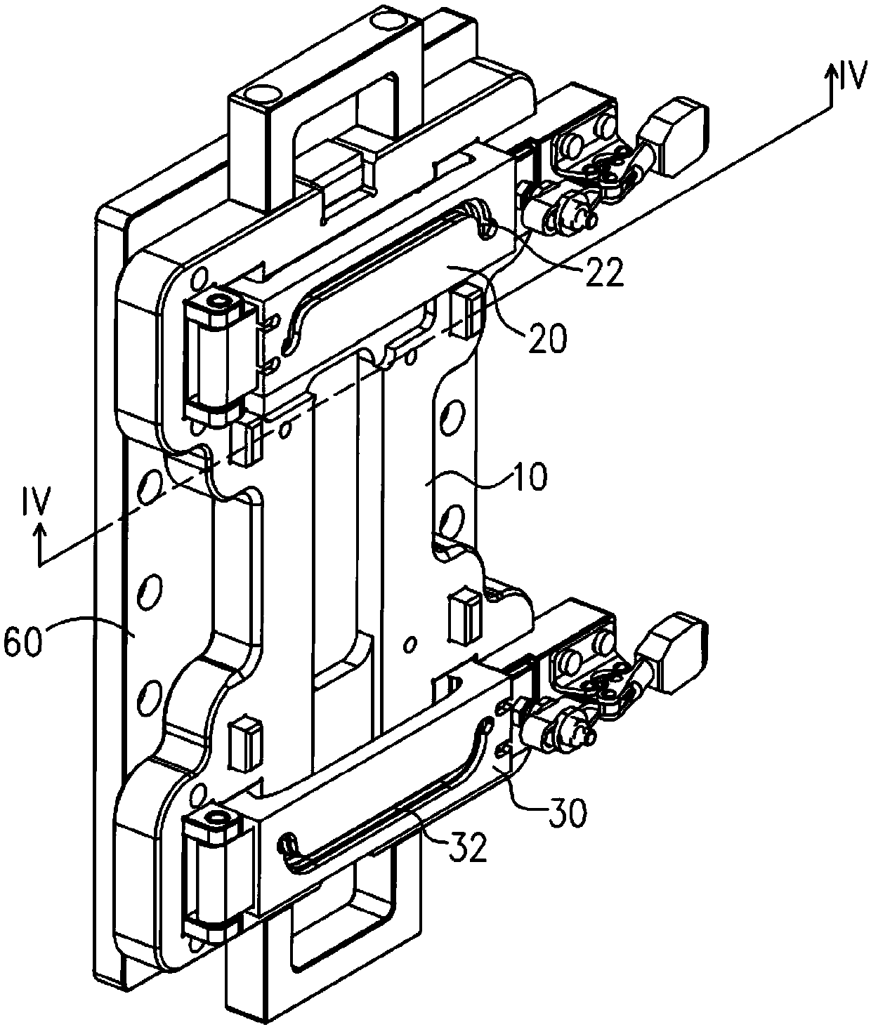
  • Dispensing jig and dispensing equipment with the dispensing jig
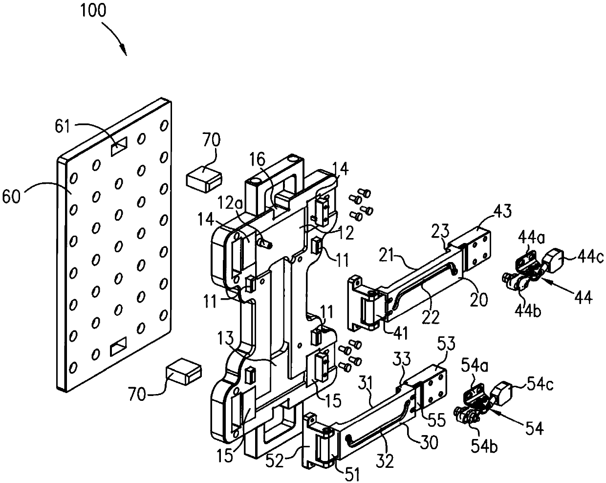
  • Dispensing jig and dispensing equipment with the dispensing jig
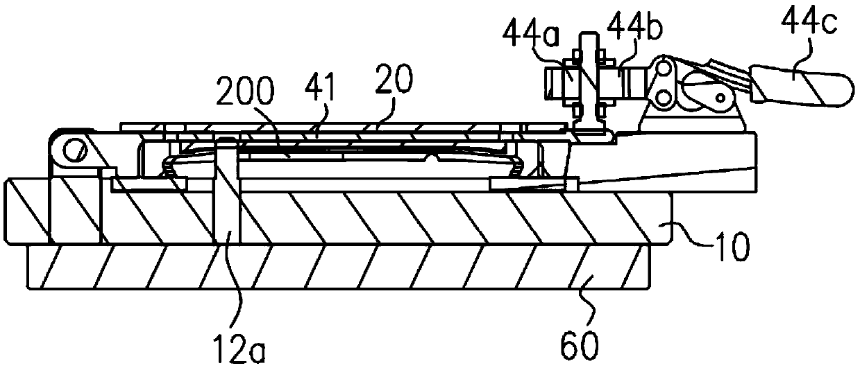
  • Dispensing jig and dispensing equipment with the dispensing jig

Examples


Embodiment Construction

[0014] The technical solutions in the embodiments of the present invention will be clearly and completely described below in conjunction with the accompanying drawings in the embodiments of the present invention. Obviously, the described embodiments are only a part of the embodiments of the present invention, rather than all the embodiments. Based on the embodiments of the present invention, all other embodiments obtained by those of ordinary skill in the art without creative work shall fall within the protection scope of the present invention.

[0015] In the description of the embodiments of the present invention, it should be understood that the orientation or positional relationship indicated by the term "thickness" is based on the orientation or positional relationship shown in the drawings, and is only for the convenience of describing the present invention and simplifying the description, and does not imply Or the device or element pointed to by the indication must have a s...


PUM


Abstract

The invention discloses a glue dispensing fixture and glue dispensing equipment with the same. The glue dispensing fixture comprises a base, a first sealing sleeve and a second sealing sleeve which are symmetrical relative to the center of the base and are arranged in a spaced manner, wherein both the first sealing sleeve and the second sealing sleeve are detachably arranged on the base, a first vacancy avoiding groove is formed in the first sealing sleeve, a second vacancy avoiding groove is formed in the second sealing sleeve, the second vacancy avoiding groove communicates with the first vacancy avoiding groove to form a placement space which is used for placing a terminal shell, a first glue dispensing groove is formed in the first sealing sleeve and is directed to one end of the terminal shell, and a second glue dispensing groove is formed in the second sealing sleeve and is directed to the other end of the terminal shell. According to the glue dispensing fixture and the glue dispensing equipment with the same, provided by the embodiments of the invention, the terminal shell is located in the placement space, and both the first sealing sleeve and the second sealing sleeve coat glue dispensing positions of the terminal shell, so that a sealed glue dispensing space can be formed, glue can be prevented from overflowing during glue dispensing, and the problem of glue overflowing is solved.

Description

Technical field [0001] The present invention relates to the technical field of equipment processing jigs, in particular to a glue dispensing jig and a glue dispensing device with the glue dispensing jig. Background technique [0002] In the molding process of the back cover of the terminal device (such as a mobile phone or a tablet computer), in order to prevent the all-metal back cover from affecting the antenna signal, it is usually necessary to set a gap on both ends of the back cover shell, and set the gap in the gap. Fill with insulating material (for example, insulating glue). At present, the insulating glue filling method of the back cover is mainly by setting a card slot with the opening facing upward on the placing platform on the dispensing equipment, and then placing the back cover directly in the slot, and then passing the dispensing head on the dispensing equipment Directly dispense glue on the gap on the back cover. However, with the above method, because the back...

Claims


Application Information

Patent Timeline
Patent Type & Authority Patents(China)
IPC IPC(8): B05C13/02B05C5/02
CPCB05C5/0208B05C13/02
Inventor 王聪
Owner GUANGDONG OPPO MOBILE TELECOMM CORP LTD
Why Eureka
Try Eureka