Stirring friction spot welding technology

A friction stir and spot welding technology, used in welding equipment, non-electric welding equipment, metal processing equipment, etc., can solve the problems of welding pressure into the pit, reducing the workload of processing, and many extrudates.

Inactive Publication Date: 2007-10-17
HUBEI UNIV OF AUTOMOTIVE TECH
View PDF0 Cites 17 Cited by
  • Summary
  • Abstract
  • Description
  • Claims
  • Application Information

AI Technical Summary

Problems solved by technology

[0003] The present invention aims at the problems of pit depth after welding and many extrudates on the surface in the prior art, and proposes a new friction stir spot weldi...

Method used


Image

  • Stirring friction spot welding technology
  • Stirring friction spot welding technology
  • Stirring friction spot welding technology

Examples


Embodiment Construction

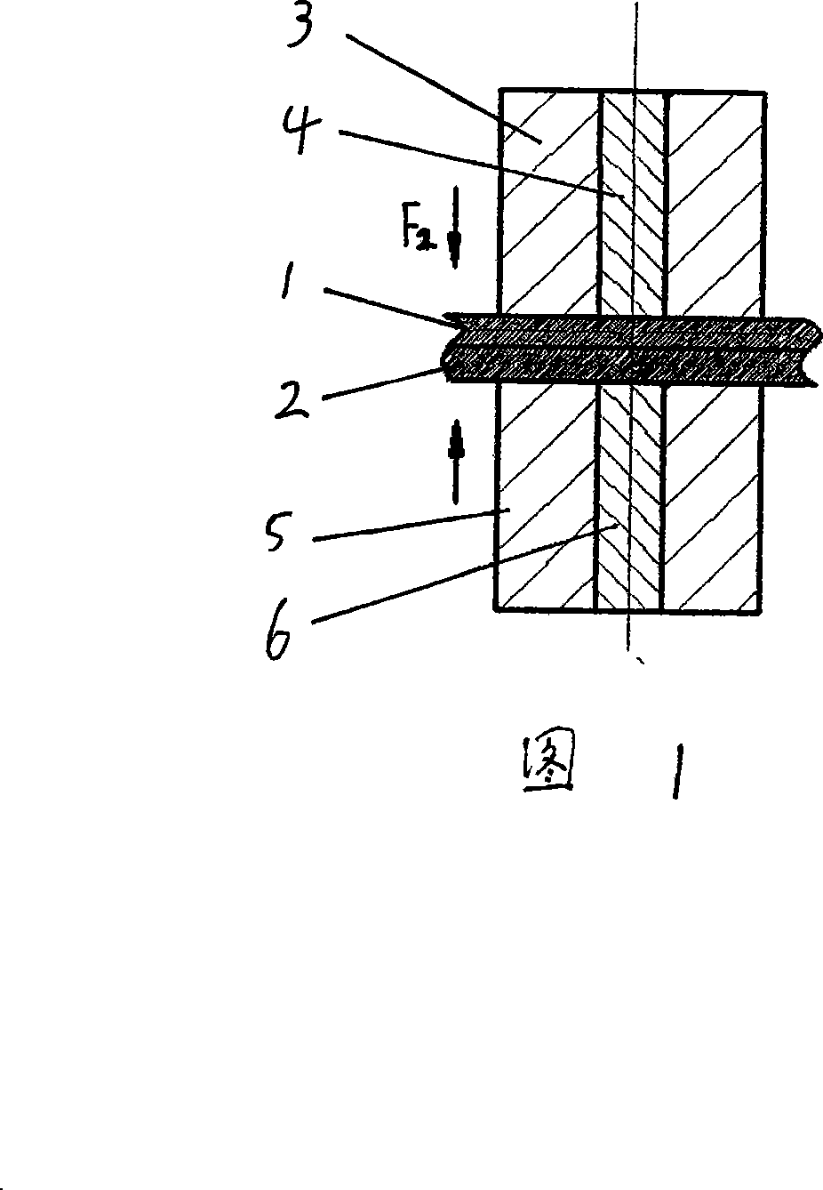
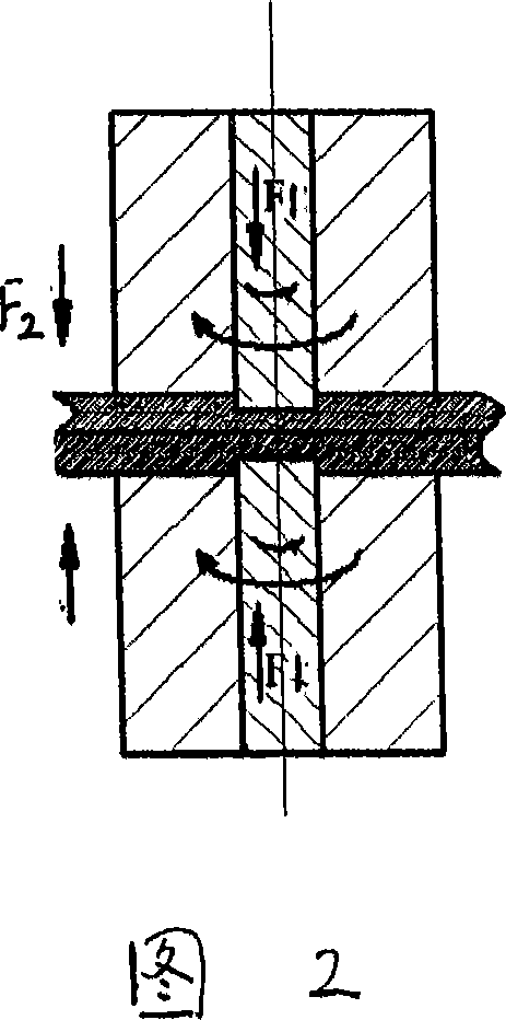
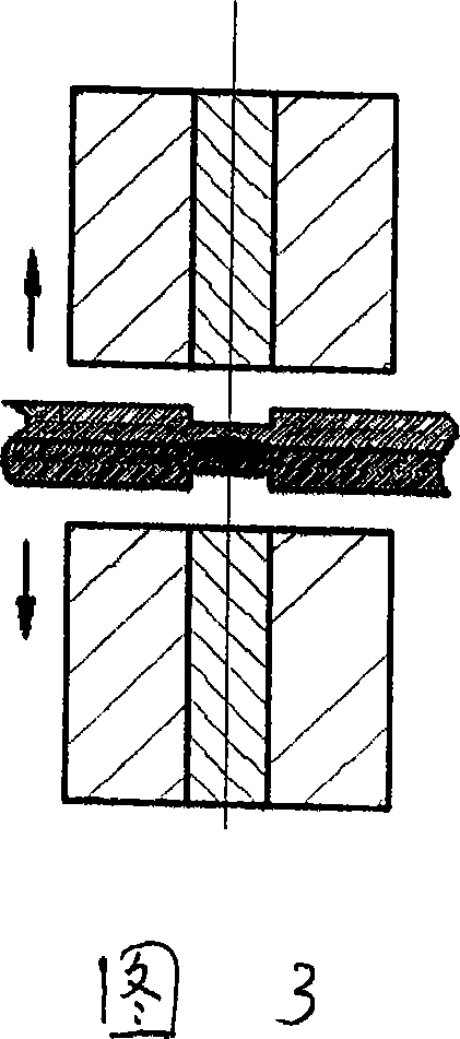
[0007] The invention designs the upper and lower shaft shoulders and the upper and lower stirring heads, and simultaneously rotates and pressurizes the upper and lower shaft shoulders and the stirring heads so that the welded parts form high quality solder joints.

[0008] Figure 1 is a schematic diagram of double-sided friction stir spot welding, 1 and 2 are parts to be welded, 3 is the upper shoulder, 4 is the upper stirring head, 5 is the lower shoulder, and 6 is the lower stirring head. The equipment parameters of the schematic diagram of the double-sided friction stir spot welding process shown in Figure 1 include: pressure F 1 , F 2 ;Rotation speed ω of shoulder 3, 5 1 ; Stirring head 4, 6 rotation speed ω 2 , and horizontal moving speed V; stirring head 4, 6 and shaft shoulder 3, 5 up and down moving stroke S; stirring head 4, 6 insertion depth h, insertion speed v 1 , the insertion residence time t, the withdrawal speed of the stirring head v 2 ; And parameters su...


PUM


Abstract

A stir friction spot welding technology adopts stir heads, and the spot welding can be carried out by agitating and rubbing from both faces simultaneously. The welding application part of the invention mainly includes four parts, that is an upper and a lower stir heads and an upper and a lower fillets. Friction heat and plastic deformation energy of the double-face friction spot welding process are produced from the upper and the lower faces; the freely rotating fillets are provided surrounding the upper and the lower stir heads in the double-face friction spot welding process, wherein the rotating of the fillets can complement defect of heat of the stir heads generated in the double-face friction spot welding process. Just because of the above characteristics, the invention can not only reduce pressure concave and extrudate of the welding surface by a half but also can increase heat generated in the welding process by one time, thus the double-face friction spot welding process can overcome defect of the friction spot welding process with single face as well as improve production efficiency.

Description

Technical field: [0001] The invention relates to a new metal material connection method. Background technique: [0002] With the development of the automobile industry, ordinary steel plates can no longer meet the requirements of the development trend of lightweight automobiles. Various non-ferrous metal materials have gradually been applied in the automobile manufacturing industry, but the poor weldability of non-ferrous metals limits the application of non-ferrous metals in the field of automobile manufacturing. Friction Stir Welding (FSW), a solid-state joining method proposed by The Welding Institute (TWI for short) in 1991, has a simple principle, few control parameters, easy automation, no radiation, The human factor in the welding process can be minimized. This technology is a low-temperature solid-phase joining technology that does not produce metal melting during the welding process. It is suitable for low-melting point alloys that are difficult to weld by fusion ...

Claims


Application Information

Patent Timeline
IPC IPC(8): B23K20/12
Inventor 董仕节黄华谢志勇
Owner HUBEI UNIV OF AUTOMOTIVE TECH
Why Eureka
Try Eureka