Construction structure and method for plugging water and sand gushing from foundation pit base

A construction method and water gushing technology, applied in infrastructure engineering, construction, etc., can solve the problems of major safety accidents, insufficient concrete volume, and extended construction period, etc., achieve a significant effect of controlling the water gushing range, prevent the expansion of the water gushing range, Simple effect of plugging material

Pending Publication Date: 2019-06-14
URBAN MASS TRANSIT ENG CO LTD OF CHINA RAILWAY 11TH BUREAU GRP
View PDF0 Cites 16 Cited by
  • Summary
  • Abstract
  • Description
  • Claims
  • Application Information

AI Technical Summary

Problems solved by technology

At present, once a large base water and sand gushing danger occurs in the conventional way, the common method is to backfill the earthwork with backpressure, backfill the concrete at the water gushing place, and at the same time assist double-fluid grouting outside the foundation pit. However, if the treatment is not timely, the amount of backfilled earthwork is insufficient, The amount of concrete is not enough, it is difficult to stop the water gushing, whether it is backfilling earthwork or concrete, it will inevitably increase the workload in the later stage, prolong the construction period and increase the cost
[0003] In the existing conventional emergency methods for water and sand inrush in the basement, whether blocking is the main method, drainage is the main method, or a combination of blocking and drainage is used, once the treatment measures are incorrect or not timely enough, the best treatment opportunity is missed, which can easily lead to major safety accidents
The losses caused are huge and the social impact is bad

Method used


Image

  • Construction structure and method for plugging water and sand gushing from foundation pit base
  • Construction structure and method for plugging water and sand gushing from foundation pit base
  • Construction structure and method for plugging water and sand gushing from foundation pit base

Examples


Embodiment Construction

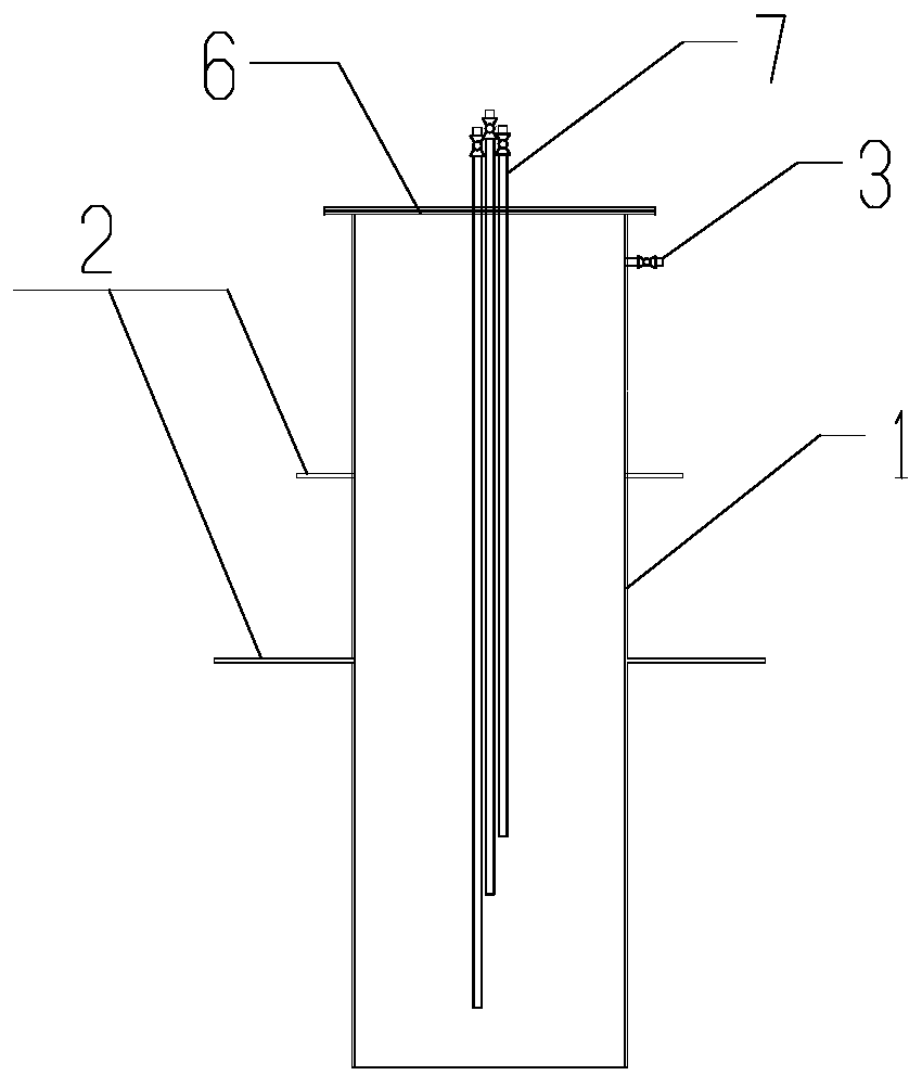
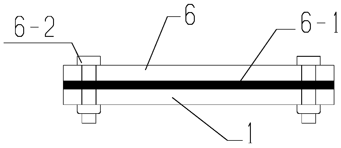
[0033] The present invention will be further described below in conjunction with the accompanying drawings and embodiments. The construction structure in the embodiment is specifically as Figure 1 to Figure 10 As shown, the following technical solutions shown in the drawings are specific solutions of the embodiments of the present invention, and are not intended to limit the scope of the claimed invention. Based on the embodiments of the present invention, all other embodiments obtained by persons of ordinary skill in the art without creative efforts fall within the protection scope of the present invention.

[0034]In the description of the present invention, it should be understood that the orientations or positional relationships indicated by the terms "upper", "lower", "inner", "outer", "left", "right" etc. are based on those shown in the accompanying drawings. Orientation or positional relationship, or the orientation or positional relationship that is usually placed wh...


PUM


Abstract

The invention provides a construction structure for plugging water and sand gushing from a foundation pit base. The construction structure comprises a steel sleeve, a concrete cover plate, a groutingreinforcing layer placed below the concrete cover, a concrete bottom plate and a concrete backfill layer of the bottom plate; the concrete construction method specifically comprises the following steps that the steel sleeve is installed with a water and sand gushing point as the circle center, and the bottom of the steel sleeve extends to the position 1m below the foundation pit base; waterstop ring plates are installed on the middle part and the upper part of the steel sleeve; high-grade early-strength concrete is poured into the steel sleeve to form the concrete cover plate, and after the final setting of the concrete, and grouting reinforcement of a disturbed soil layer is carried out within the range of the depth range of 1.0 m below the bottom of the cover plate within the scope of the cover plate of the concrete cover plate in the periphery of the steel sleeve; then a drain valve in the side wall of the steel sleeve is opened, and a sleeve opening of the steel sleeve is plugged through a sealing flange steel cover plate; and finally, the drain valve in the side wall of the steel sleeve is closed, and grouting into the steel sleeve is carried out for plugging the water gushingthrough a grouting pipe reserved in the steel cover plate. According to the construction structure and method for plugging the water and sand gushing from the foundation pit base, the plugging speedis high, the effect is good, the cost is low, and the control effect of a water gushing range is remarkable.

Description

technical field [0001] The invention relates to the construction field of foundation pit open excavation method, in particular to a construction structure and method for blocking water and sand gushing at the base of the foundation pit. Background technique [0002] In today's urban construction, there are more and more deep and large foundation pits, especially subway projects are mostly located in the center of the city. Deep foundation pit projects are generally located in areas where buildings and various pipelines are relatively dense. The construction environment of deep foundation pit projects is relatively complicated. If effective measures cannot be taken to reduce the impact on the surrounding environment during deep foundation pit construction, especially if water gushing occurs If effective control measures are not taken in time when the sand is in danger, it is easy to cause pipeline breakage around the deep foundation pit, cracking of surrounding buildings, gro...

Claims


Application Information

Patent Timeline
Patent Type & Authority Applications(China)
IPC IPC(8): E02D19/12E02D19/16
Inventor 冯亚辉李杰李飞鹏彭刚朱殿君郑志波陆国平陈俊杰
Owner URBAN MASS TRANSIT ENG CO LTD OF CHINA RAILWAY 11TH BUREAU GRP
Why Eureka
Try Eureka