Button structure and mechanical keyboard
A button and keycap technology, which is applied in computing, electrical components, electric switches, etc., can solve the problems of low motion stability, large button structure, complex structure, etc., and achieve improved motion stability, small overall volume, and simple structure Effect
- Summary
- Abstract
- Description
- Claims
- Application Information
AI Technical Summary
Problems solved by technology
Method used
Image


Examples
Embodiment 1
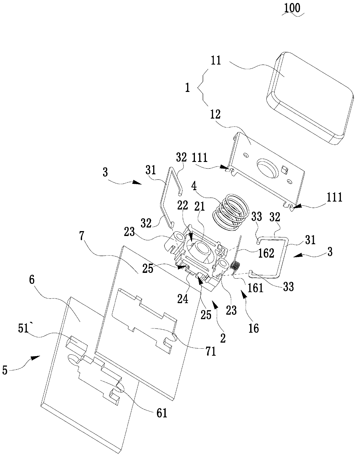
[0043] Please refer to figure 1 with figure 2 The key structure 100 provided by the embodiment of the present invention includes a key cap assembly 1 , a key shaft seat 2 , two support rods 3 , a spring 4 , a trigger assembly 5 , a circuit board 6 and a bottom plate 7 . The key cap assembly 1 , the key shaft seat 2 , the bottom plate 7 and the circuit board 6 are stacked sequentially from top to bottom, and the key shaft seat 2 is installed on the bottom plate 7 . The support rod 3 includes a horizontal portion 31 and two vertical portions 32, the two vertical portions 32 are respectively formed by extending radially outward from both ends of the horizontal portion 31, the two vertical portions 32 are located on the same side of the horizontal portion 31, and the two The vertical part 32 is clamped on the key shaft seat 2 , the horizontal part 31 is pivotally connected to the keycap assembly 1 , and the vertical parts 32 on the same side of the two support rods 3 are on the sa...
Embodiment 2
[0054] Please refer to Figure 10 with Figure 11 The difference from the first embodiment above is that the receiving part is two abutting elastic pieces 51``, the two elastic pieces 51`` are oppositely arranged on the circuit board 6 and pass through the bottom plate 7, and the triggering part is an isolation plate 52``. Specifically, the isolation plate 52 ″ is L-shaped, including a vertical section 521 ″ and a horizontal section 522 ″ vertically connecting the vertical section 521 ″. When the keycap assembly 1 is stationary relative to the key shaft seat 2, the horizontal section 522`` of the isolation plate 52`` is inserted between the two shrapnels 51`` to prevent the two shrapnels 51`` from contacting each other, that is, the circuit board 6 is in an open circuit state; when the isolation plate 52`` goes down with the keycap assembly 1, the vertical section 521`` of the isolation plate 52`` is inserted between the two shrapnels 51``, because the width of the vertical s...
Embodiment 3
[0056] Please refer to Figure 12 with Figure 13 , the difference from the first embodiment above is that the receiving part is the transmitting tube 51a``` and the receiving tube 51b``` located on both sides of one of the guide tubes 23, and the transmitting tube 51a``` and the receiving tube 51b``` Relatively arranged on the circuit board 6 and passing through the bottom plate 7, a light-transmitting hole 231 for the receiving tube 51b```to communicate with the transmitting tube 51a```is opened on the guide tube 23, that is, the transmitting tube 51a``` emits The beam of light passes through the light hole 231 and is received by the receiving tube 51b```. At this time, the circuit of the circuit board 6 is in an open circuit state. The trigger part is one of the second guide posts 14. When the second guide post 14 is inserted into the corresponding guide tube 23, the second guide post 14 blocks the light-transmitting hole 231, so that the transmitting tube 51a``` and the r...
PUM
 Abstract
Description
Claims
Application Information
 - R&D
- Intellectual Property
- Life Sciences
- Materials
- Tech Scout
- Unparalleled Data Quality
- Higher Quality Content
- 60% Fewer Hallucinations
Browse by: Latest US Patents, China's latest patents, Technical Efficacy Thesaurus, Application Domain, Technology Topic, Popular Technical Reports.
© 2025 PatSnap. All rights reserved.Legal|Privacy policy|Modern Slavery Act Transparency Statement|Sitemap|About US| Contact US: help@patsnap.com