
Clip pushing device of tool board and clip pushing system employing same

A technology for pushing devices and fixture boards, which is applied to the positioning of circuit board tools, PCB positioning during processing, and electrical components. It can solve the problems of increasing labor force, slowing down production efficiency, and low production efficiency, so as to speed up production efficiency. , Reduce production burden, reduce production cost effect

Active Publication Date: 2017-12-08
GUANGDONG LXD ROBOTICS CO LTD
View PDF5 Cites 0 Cited by
  • Summary
  • Abstract
  • Description
  • Claims
  • Application Information

AI Technical Summary

Problems solved by technology

In ordinary production, after the PCB board is produced in the production line, the last process is to manually put the PCB circuit board into the jig board, and then buckle the button of the jig board to lock the PCB board on the jig board. It increases the labor force and slows down the production efficiency of enterprises.
In order to solve this problem, automated assembly has appeared at present, and the adopted scheme is as follows: first manually open the button of the jig board, put the jig board on the transportation line, and then put the PCB circuit board on the jig board, Finally, the mechanical button mechanism is used to fasten the button of the jig plate, but there is still the manual operation of opening the button of the jig board, and the production efficiency of manual operation is not high. When it is fully opened and put on the transportation line, the PCB will not be put into the fixture board, resulting in stagnation of final production

Method used


Image

  • Clip pushing device of tool board and clip pushing system employing same
  • Clip pushing device of tool board and clip pushing system employing same
  • Clip pushing device of tool board and clip pushing system employing same

Examples


Embodiment Construction

[0031] The technical solutions of the present invention will be further described below in conjunction with the accompanying drawings and through specific implementation methods.

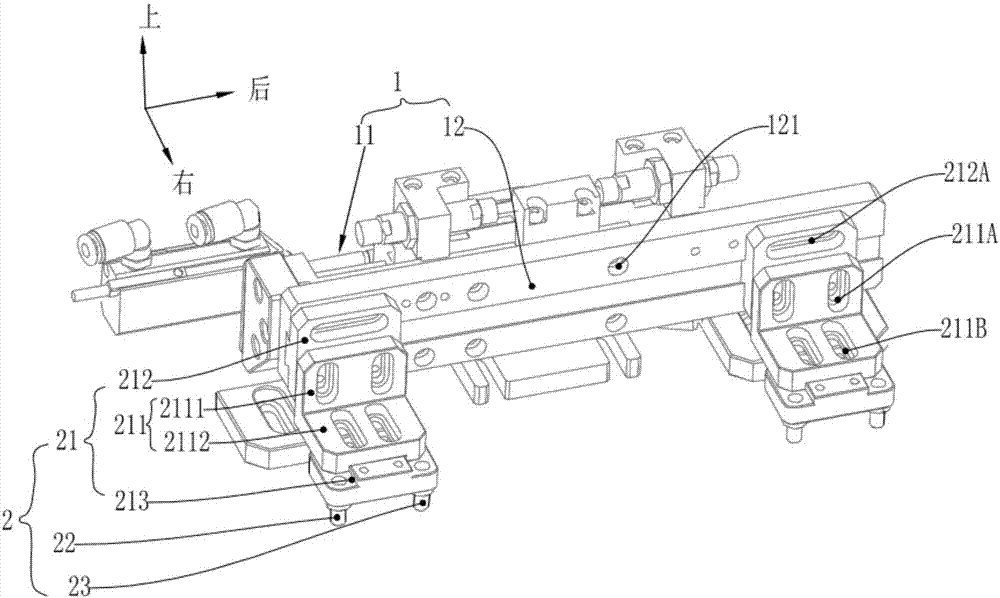
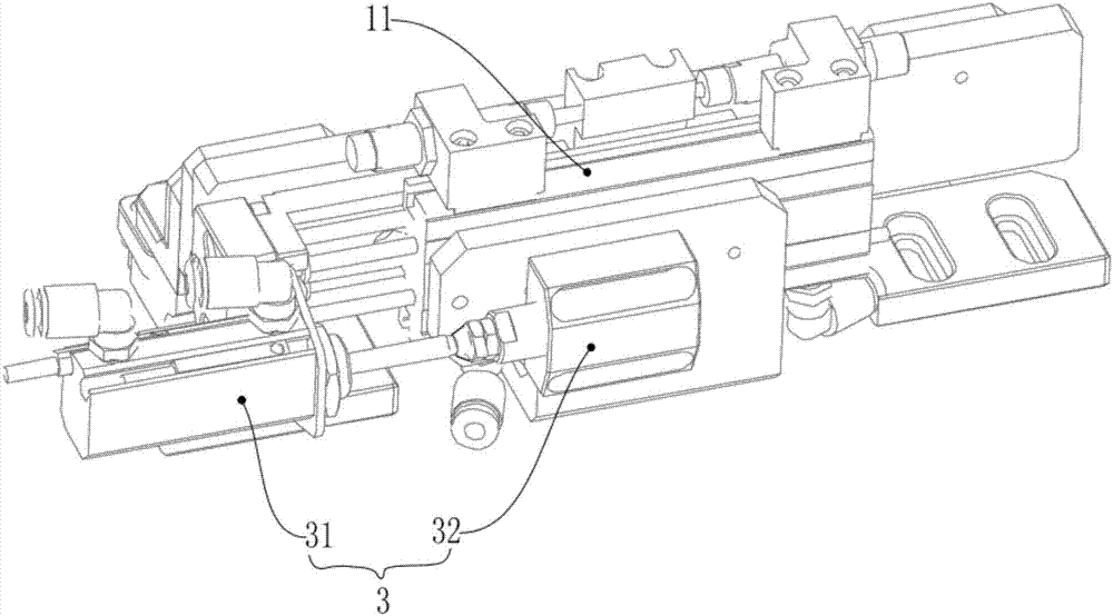
[0032] A buckle pushing device for a jig plate, comprising an action component 1 and a toggle component 2;

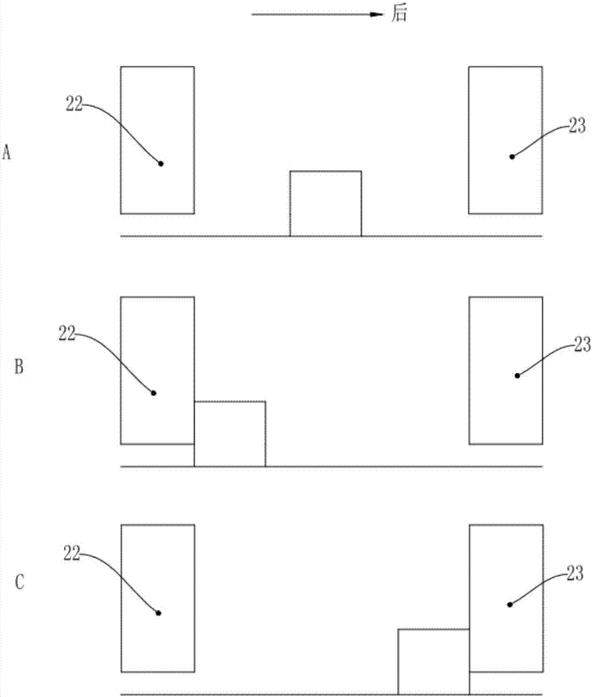
[0033] The buckle assembly 2 includes a mounting base 21, a first pin 22 and a second pin 23; the first pin 22 and the second pin 23 are respectively arranged on the front and rear sides of the bottom of the mounting base 21, and are vertically Straight down; the distance between the first pin 22 and the second pin 23 is greater than the width of the action end of the button on the jig plate;

[0034] The action component 1 is connected to the mounting base 21 for driving the button component 2 to move back and forth.

[0035] The width of the action end of the toggle on the jig board is the end that is in contact with the toggle assembly 2, and the other end is the end that limits the PCB c...


PUM


Abstract

The invention relates to the technical field of electric component and part assembling and processing. The clip pushing device of a tool board includes an action assembly and a toggle assembly. The toggle assembly includes a mounting base, a first pin and a second pin. The first pin and the second pin are arranged on the front side and the rear side of the bottom part of the mounting base and are both arranged vertically downward. The distance between the first pin and the second pin is greater than the width of an action end of the toggle on the tool board. The action assembly is connected to the mounting base and is used for driving the toggle assembly to move back and forth. A clip pushing system employing the above clip pushing devices includes two clip pushing devices arranged opposite to each other in a spaced manner.

Description

technical field [0001] The invention relates to the technical field of assembly and processing of electronic components, in particular to a buckle pushing device for a jig plate and a buckle pushing system using the same. Background technique [0002] PCB circuit board, also known as printed circuit board, is the provider of electrical connection for electronic components. In ordinary production, after the PCB board is produced in the production line, the last process is to manually put the PCB circuit board into the jig board, and then buckle the button of the jig board to lock the PCB board on the jig board. It increases the labor force and slows down the production efficiency of enterprises. In order to solve this problem, automated assembly has appeared at present, and the adopted scheme is as follows: first manually open the button of the jig board, put the jig board on the transportation line, and then put the PCB circuit board on the jig board, Finally, the mechanic...

Claims


Application Information

Patent Timeline
Patent Type & Authority Applications(China)
IPC IPC(8): H05K3/00
CPCH05K3/0008H05K2203/15
Inventor 黄学志曾磊
Owner GUANGDONG LXD ROBOTICS CO LTD
Learn More