
Electronic device and method for manufacturing same

A technology of electronic devices and light emitting devices, which is applied in the direction of electrical equipment casings/cabinets/drawers, electrical components, casings/cabinets/drawer components, etc., and can solve problems such as limiting design freedom and manufacturing costs

Active Publication Date: 2017-12-08
ROHDE & SCHWARZ GMBH & CO KG
View PDF8 Cites 0 Cited by
  • Summary
  • Abstract
  • Description
  • Claims
  • Application Information

AI Technical Summary

Problems solved by technology

[0003] However, the coupling of LEDs and light guide plates limits design freedom and leads to additional manufacturing costs

Method used


Image

  • Electronic device and method for manufacturing same
  • Electronic device and method for manufacturing same
  • Electronic device and method for manufacturing same

Examples


Embodiment Construction

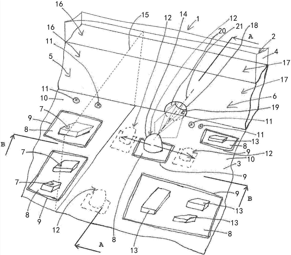
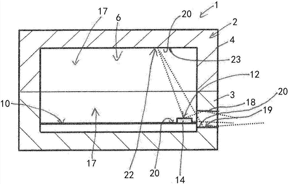
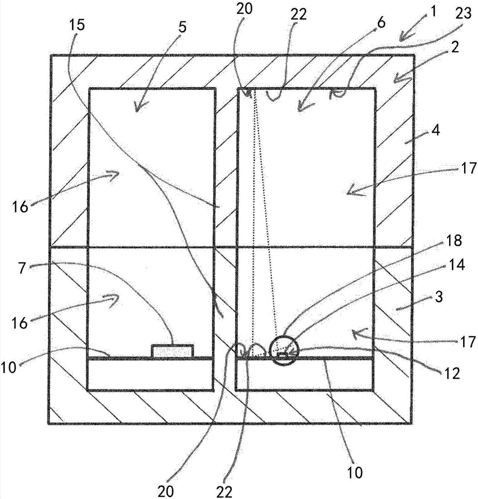
[0033] exist figure 1 , 2 and 3, an electronic device 1 according to an embodiment of the present invention is shown. figure 1 A schematic diagram of a part of the electronic device 1 is shown. further, figure 2 show the basis figure 1 The cross-section A-A of the electronic device, image 3 is based on figure 1 Cross-section B-B of the electronic device. It should be noted, figure 1 , 2 and 3 are only schematic and not to scale. Further, connections including electrical connections of the different components of the electronic device 1 , especially between these components, are not shown in the figures for the sake of clarity.

[0034] Such as figure 1 , 2 As shown in and 3 , the electronic device 1 includes a casing 2 , and the casing 2 includes a first half 3 and a second half 4 . The housing 2 is further subdivided into at least a first chamber 5 and a second chamber 6 .

[0035] In the first cavity 5 one or more electronic components 7 are housed. A plurali...


PUM


Abstract

The invention provides an electronic device and a method for manufacturing the same (1). The electronic device comprises a shell (2) and at least one light-emitting device (12), wherein the shell is electromagnetically shielded, the at least one light-emitting device (12) is arranged in the shell (2) and is used for indicating at least one state of the electronic device (1), an opening (18) is formed in the shell (2) and is used for guiding light from the at least one light-emitting device (12) to a boundary of the shell (2), and the opening (18) is provided with a reflective surface (19) so that the light from the at least one light-emitting device (12) is reflected and guided to the boundary.

Description

technical field [0001] The present invention relates to an electronic device and a method of manufacturing the same, and in particular to a measuring device for a mobile phone which is electromagnetically shielded and also indicates at least one state of the electronic device to the outside. Background technique [0002] In EP1189291A2 a chip-type light emitting diode is disclosed. Chip LEDs are mounted on the motherboard. The motherboard is formed with a hole through which the body portion of the chip light emitting diode passes from the rear surface of the motherboard and protrudes out of the front surface side. The chip type light emitting diodes are positioned close to the side end surfaces of the light guide plate mounted on the front surface side of the motherboard. The side end surfaces of the light guide plate are straight in the vertical direction and no reflective surface is formed. When light is emitted from the light emitting diode element of the light emittin...

Claims


Application Information

Patent Timeline
IPC IPC(8): H05K5/02
CPCH05K5/0217
Inventor 赫曼·格罗尔海因里希·比希尔
Owner ROHDE & SCHWARZ GMBH & CO KG
Learn More