Sphere zone coupling of magnetic devices and multiple applications

a magnetic device and sphere zone technology, applied in the field of magnetic coupling, can solve the problems of less efficiency of magnetic devices, less efficiency of magnetic couplings, and high noise of mechanical gears, and achieve the effects of more freedom of axial and mechanism design, greater torque, and more freedom of multiple outputs or torque transmissions

Inactive Publication Date: 2014-01-16
CHENG HSI CHIEH
View PDF3 Cites 22 Cited by
  • Summary
  • Abstract
  • Description
  • Claims
  • Application Information

AI Technical Summary

Benefits of technology

[0013]In other embodiments, the present invention provides mechanism design of drive with several transmitting gears to transport driving forces to output rotor and axle. Thus greater torque can be transmitted from the combination of multiple sphere zone couplings to the specified output rotor. Additionally different gear rotors can output torque as different transmitting systems in different directions from the drive. So in the coordinating system some gear rotors can be transporting gears and some rotors can be output gears. The mechanism design has more freedom for multiple outputs or torque transmissions.
[0014]In further embodiments of the present invention, instead of rotating the drive rotor when the carrier frame of gear rotors rotates with constant speed, the output rotor can rotate with ratio speed plus carrier driving speed.

Problems solved by technology

Mechanical gear will generate much noise, vibration and wear than magnetic gear.
Thus make the magnetic devices work less efficient.
Because a lot of the magnetic couplings are less efficient and cannot assist in transferring torque, a

Method used


Image

  • Sphere zone coupling of magnetic devices and multiple applications
  • Sphere zone coupling of magnetic devices and multiple applications
  • Sphere zone coupling of magnetic devices and multiple applications

Examples


Embodiment Construction

[0030]Detailed descriptions of preferred embodiments are provided herein. It is to be understood, however, that the present invention may be embodied in various forms. Therefore, specific details disclosed herein are not to be interpreted as limiting, but rather as a basis for the claims and as a representative basis for teaching one skilled in the art to employ the present invention in virtually any appropriately detailed system, structure or manner.

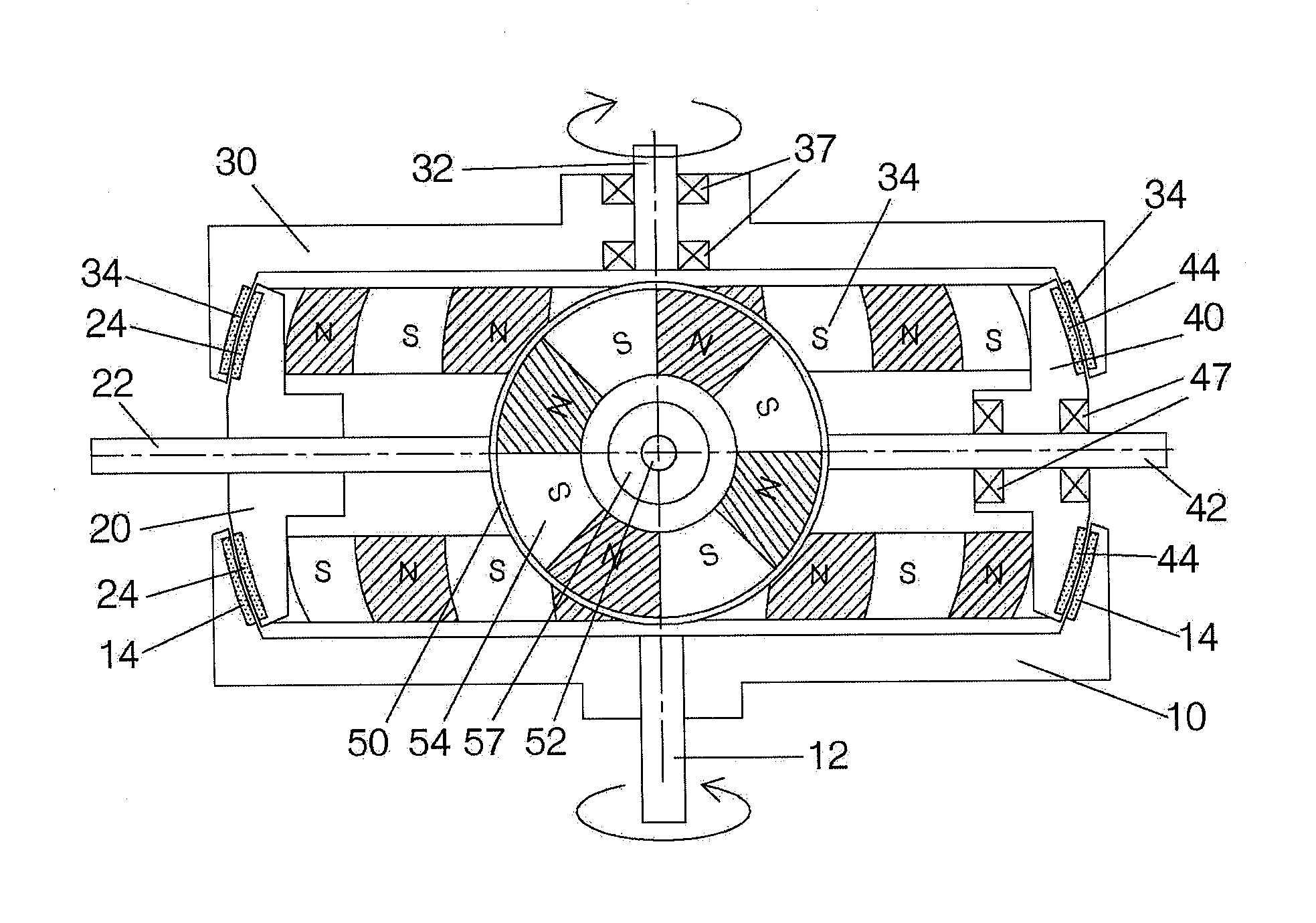
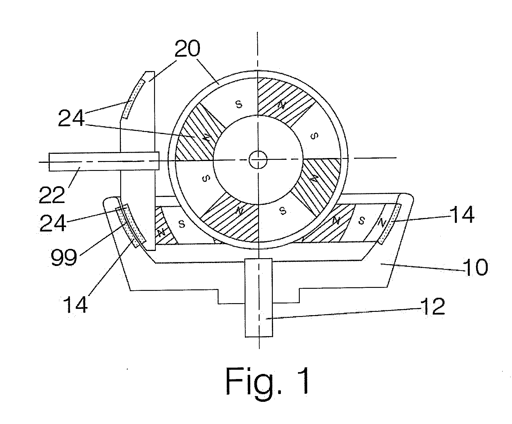
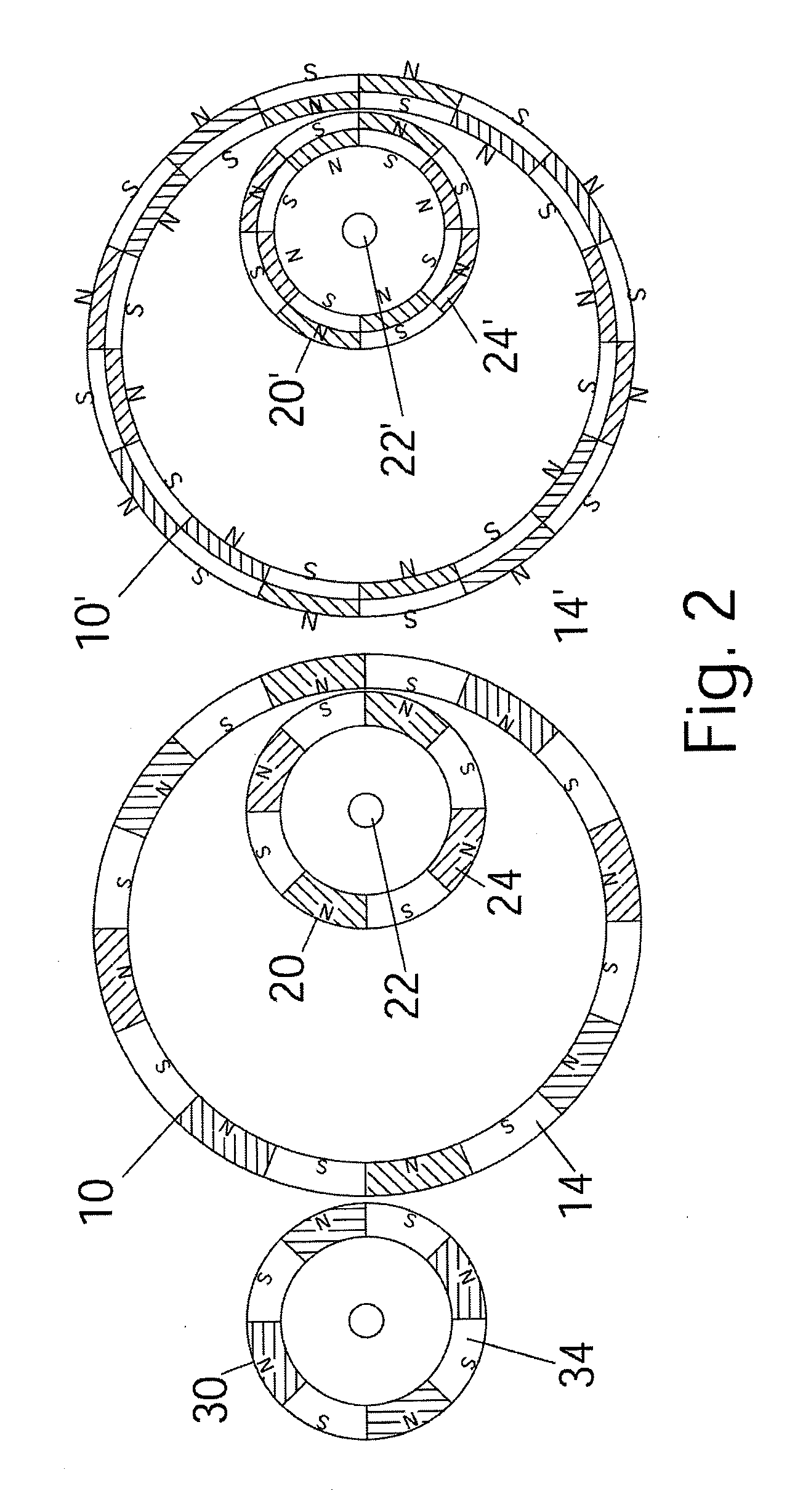
[0031]In FIG. 1, a first rotor 10 with magnetic array 14 in annular and arranged to comprise a sphere zone face. The magnetic array is provided with a plurality of magnetic poles of comprising opposite polarity next to each other in turn. The first rotor 10 is supported for rotation about a first axle 12.

[0032]A second rotor 20 is provided with magnetic array 24 in annular and arranged to comprise a sphere zone face which has almost the same sphere radius as the sphere zone face of the first rotor, but the zone radius can be the same or...


PUM


Abstract

A sphere zone coupling of magnetic devices has a first rotor containing permanent magnet array and a second rotor. The first rotor and the second rotor have the sphere zone surfaces forming from magnetic array or similar of almost the same sphere radius facing with constant air gap at overlapped area. The axle of the first rotor and the axle of the second rotor are concentric and non-coaxial. The second rotor has permanent magnet array, ferromagnetic or conductive material to couple with the first rotor at the sphere zone surfaces. The rotation of the first rotor causes magnetic force to drive the second rotor. The transmission ratio will depend on the average zone radius ratio of two coupling rotors and the pair number ratio of magnets in magnetic arrays.

Description

BACKGROUND OF THE INVENTION[0001]1. Field of the invention[0002]The present invention relates generally to magnetic coupling, and more particularly to sphere zone coupling of magnetic rotors for drive devices, and multiple applications can apply in magnetic drive mechanism and combination to work for efficient torque transmission.[0003]2. Description of the Related Art[0004]Mechanical gear will generate much noise, vibration and wear than magnetic gear. Mechanical gears need lubrication and more maintenance for wear and tear. While magnetic gear can provide better benefits from mentioned problem in transmission system. Recent advances in the material research have developed powerful magnets and applied in wide range of use for magnetic transmission. Thus make the magnetic gear to be workable in industrial application.[0005]Generally magnetic coupling of gear is the magnet arrays arranged at a circumferential radius to work with cylindrical or disk-shaped drive rotating members. In s...

Claims


Application Information

Patent Timeline
IPC IPC(8): H02K49/00
CPCH02K49/102
Inventor CHENG, HSI-CHIEH
Owner CHENG HSI CHIEH
Why Eureka
Try Eureka