Dust collector

A technology for vacuum cleaners and dust cups, which is applied in the direction of vacuum cleaners, electrical components, cleaning equipment, etc. It can solve the problems of potential safety hazards in vacuum cleaners and easy prolapse of power cords, and achieve the effect of preventing power cords from protruding

Active Publication Date: 2017-12-12
JIANGSU MIDEA CLEANING APPLIANCES
View PDF6 Cites 1 Cited by
  • Summary
  • Abstract
  • Description
  • Claims
  • Application Information

AI Technical Summary

Problems solved by technology

[0002] During the use of the existing vacuum cleaner, the power cord is easy to come out, which makes the vacuum cleaner a potential safety hazard during use

Method used


Image

  • Dust collector
  • Dust collector
  • Dust collector

Examples


Embodiment Construction

[0035] Embodiments of the present invention are described in detail below, examples of which are shown in the drawings, wherein the same or similar reference numerals designate the same or similar elements or elements having the same or similar functions throughout. The embodiments described below by referring to the figures are exemplary only for explaining the present invention and should not be construed as limiting the present invention.

[0036] Refer below Figure 1-Figure 9 A specific structure of the vacuum cleaner 1000 according to the embodiment of the present invention will be described.

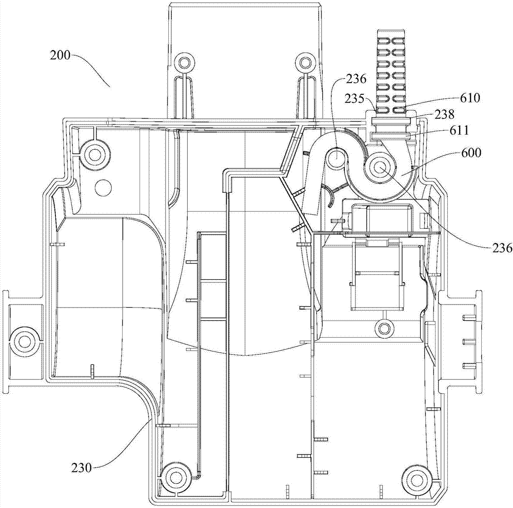
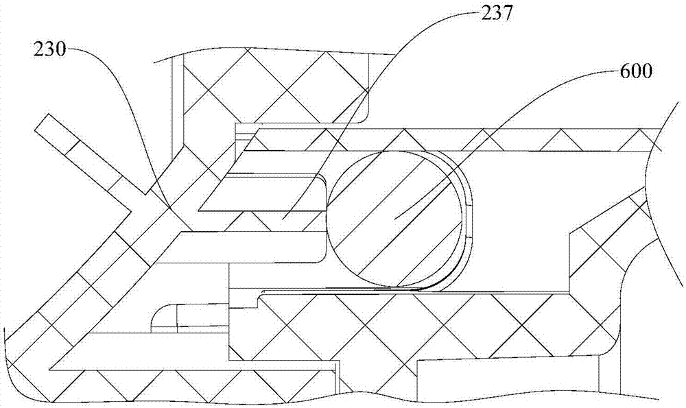
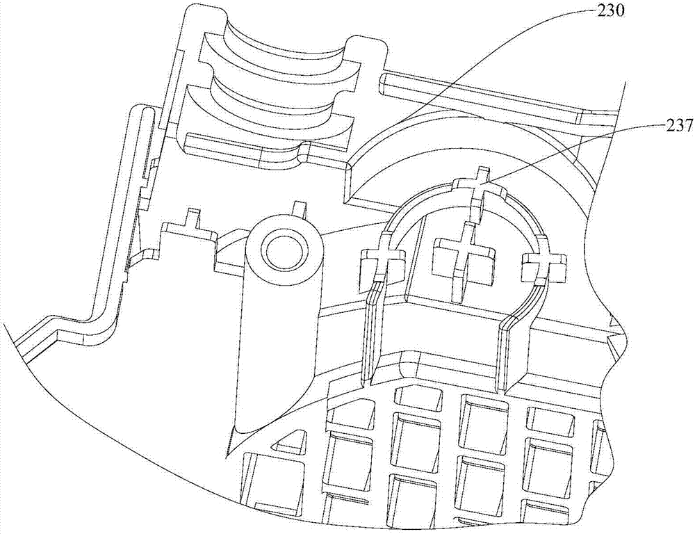
[0037] Such as figure 1 , Figure 7 As shown, a vacuum cleaner 1000 according to an embodiment of the present invention has a ground brush assembly 100 , a motor assembly 200 , a body assembly 300 , a dust cup assembly 400 and a power cord 600 .

[0038] The motor assembly 200 is connected to the ground brush assembly 100, the fuselage assembly 300 is connected to the rear end ...


PUM


Abstract

The invention discloses a dust collector. The dust collector comprises a floor brush assembly, a motor assembly, a machine body assembly, a dust cup assembly and a power line, wherein the motor assembly is connected with the floor brush assembly, the machine body assembly is connected to the back end of the motor assembly, the dust cup assembly is detachably connected to the top of the motor assembly and detachably connected to the front side of the machine body assembly, and the power line is connected with the motor assembly. The motor assembly comprises a motor cover and a motor, wire penetrating openings are formed in the motor cover, a plurality of winding columns are arranged at the portions, adjacent to the wire penetrating openings, in the motor cover, one end of the power line extends into the motor cover from the wire penetrating openings, and the power line is wound around the multiple winding columns in an S shape; the motor is arranged in the motor cover and connected with the power line. According to the dust collector in the embodiment, as the multiple winding columns are arranged at the portions, adjacent to the wire penetrating openings, of the motor cover of the dust collector, and the power line is wound around the multiple winding columns in the S shape, sliding of the power line is limited, and it can be avoided that the phenomenon that the power line is pulled away occurs in the working process of the dust collector.

Description

technical field [0001] The invention relates to the field of household appliances, in particular to a vacuum cleaner. Background technique [0002] During the use of the existing vacuum cleaner, the power cord is easy to come out, so that there is a potential safety hazard during the use of the vacuum cleaner. Contents of the invention [0003] The present invention aims to solve at least one of the technical problems existing in the prior art. For this reason, the present invention proposes a vacuum cleaner, the power cord of the vacuum cleaner is not easy to come out. [0004] The vacuum cleaner according to the embodiment of the present invention includes: a ground brush assembly; a motor assembly, the motor assembly is connected to the ground brush assembly; a fuselage assembly, the fuselage assembly is connected to the rear end of the motor assembly; a dust cup Assembly, the dust cup assembly is detachably connected to the top of the motor assembly and detachably co...

Claims


Application Information

Patent Timeline
IPC IPC(8): A47L5/22A47L9/26A47L9/00
CPCA47L5/22A47L9/00A47L9/26
Inventor 任开强郭怡隽王华威沈兆祥朴永哲
Owner JIANGSU MIDEA CLEANING APPLIANCES
Why Eureka
Try Eureka