Supercharge Your Innovation With Domain-Expert AI Agents!

Iron wire stapling device

A technology for stapling and iron wire, applied in the direction of binding, etc., can solve the problems of single binding thickness, the height of the worktable of the iron wire stapling device and the position of the tightening hook device cannot be adjusted, affecting the operation of operators, etc., so as to save costs and improve Binding quality, the effect of improving convenience

Inactive Publication Date: 2017-12-12
BEITANG JUNZHI PRINTING PAPER PROCESSING FACTORY
View PDF0 Cites 0 Cited by
  • Summary
  • Abstract
  • Description
  • Claims
  • Application Information

AI Technical Summary

Problems solved by technology

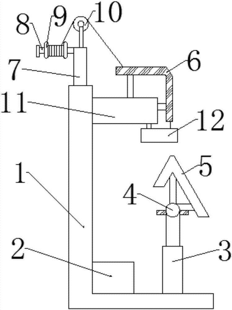
The existing wire stapling devices generally can only be used for saddle stitching and flat stapling, and the height of the working table of the wire stapling device and the position of the hook device cannot be adjusted, and different operators adapt to different heights, which affects the operation Operation of personnel
The existing wire stapler also has the problem of single binding thickness

Method used


Image

  • Iron wire stapling device
  • Iron wire stapling device
  • Iron wire stapling device

Examples


Embodiment Construction

[0016] The following will clearly and completely describe the technical solutions in the embodiments of the present invention with reference to the accompanying drawings in the embodiments of the present invention. Obviously, the described embodiments are only some, not all, embodiments of the present invention. Based on the embodiments of the present invention, all other embodiments obtained by persons of ordinary skill in the art without making creative efforts belong to the protection scope of the present invention.

[0017] In the description of the present invention, it should be noted that the orientation or positional relationship indicated by the terms "vertical", "upper", "lower" and "horizontal" are based on the orientation or positional relationship shown in the drawings, and are only for It is convenient to describe the present invention and simplify the description, but does not indicate or imply that the device or element referred to must have a specific orientati...


PUM


Abstract

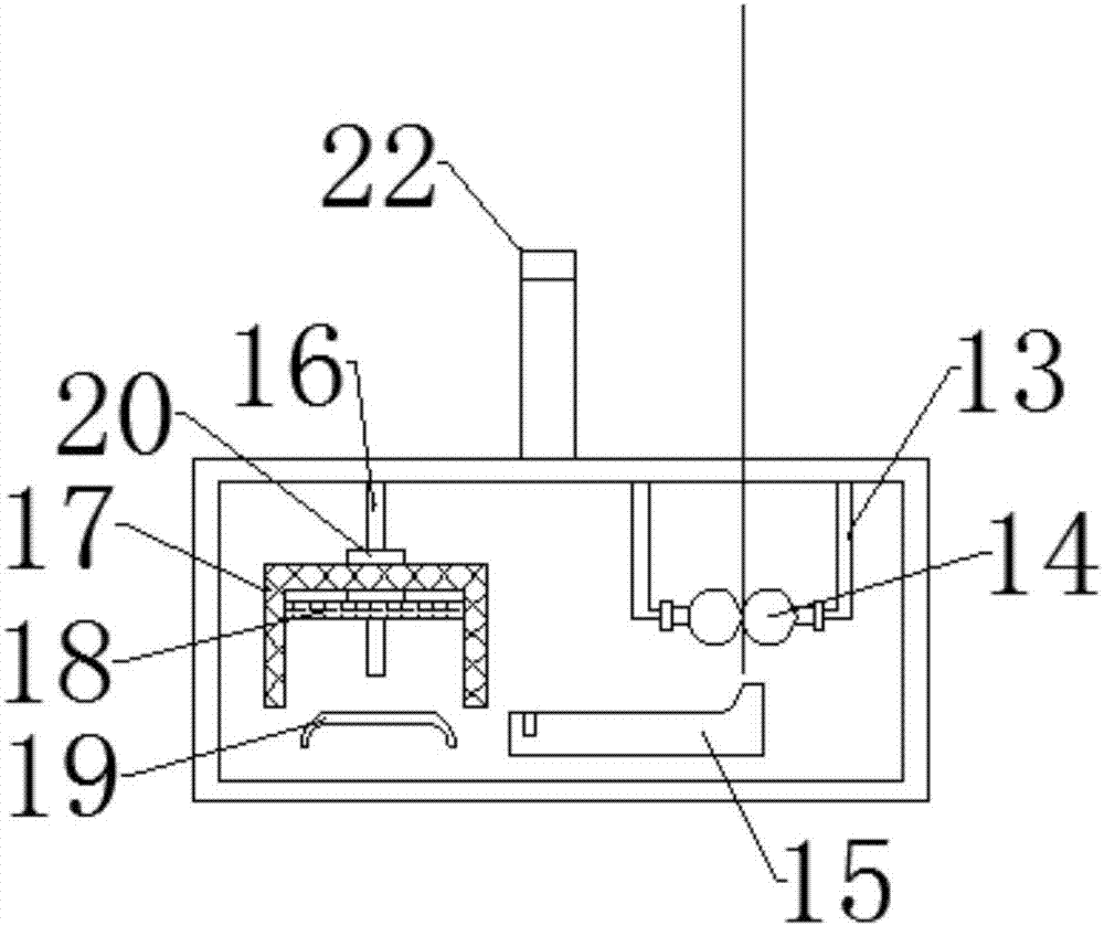
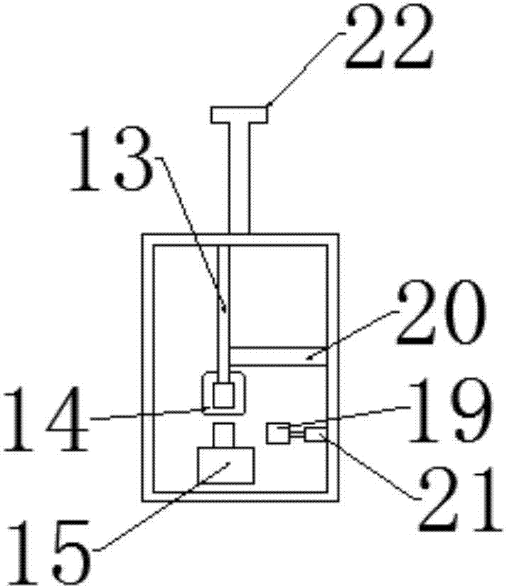
The invention discloses an iron wire stapler, which comprises a frame, a motor and a hook device. A connecting rod is fixedly connected to the left side of the supporting rod, and a wire turn is connected to the shaft of the connecting rod. The top end of the supporting rod passes through The short rod is rotatably connected with a guide wheel, and a first telescopic rod is installed on the right side of the bottom end of the frame. The first telescopic rod is provided with a rotating shaft, and one end of the rotating shaft is fixedly connected with a workbench. It includes a fixed rod, a wire feeding table, a wire feeding roller, a forming table, a chute, a slider, a nailing board, an extruding board and a second telescopic rod. This new type of use adds a dual-purpose workbench, so that the device can perform saddle stitching and flat stitching, which saves costs. By adding a length regulator, the length of the iron wire can be adjusted according to the thickness of the items to be bound, and the quality of binding can be improved. A slide bar is added so that the hook device can be displaced horizontally according to the binding requirements, which improves the convenience of the device.

Description

technical field [0001] The invention relates to the technical field of printing-related equipment, in particular to a wire stapler. Background technique [0002] The wire staple device is a staple device suitable for mass production, with good binding quality and high binding precision, and uses disc-shaped iron wire as the binding material. The existing wire stapling devices generally can only be used for saddle stitching and flat stapling, and the height of the working table of the wire stapling device and the position of the hook device cannot be adjusted, and different operators adapt to different heights, which affects the operation personnel operations. There is also the problem that the binding thickness is single in the existing wire stapler. Therefore, I provide a wire stapler. Contents of the invention [0003] The object of the present invention is to provide a wire stapler to solve the problems raised in the above-mentioned background technology. [0004] I...

Claims


Application Information

Patent Timeline
IPC IPC(8): B42B4/00
CPCB42B4/00
Inventor 余学润
Owner BEITANG JUNZHI PRINTING PAPER PROCESSING FACTORY
Features
  • R&D
  • Intellectual Property
  • Life Sciences
  • Materials
  • Tech Scout
  • Unparalleled Data Quality
  • Higher Quality Content
  • 60% Fewer Hallucinations
Learn More