Clamping method applicable to tensile strength test of cylindrical part

A technology of tensile strength and clamping method, which is applied in the direction of strength characteristics, measuring devices, instruments, etc., can solve the problems of unsatisfactory clamping effect of columnar parts, and achieve small bayonet expansion, easy clamping and locking, and expansion A large amount of effect

Inactive Publication Date: 2017-12-12
API ZC PRECISION INSTUMENT CO LTD
View PDF7 Cites 1 Cited by
  • Summary
  • Abstract
  • Description
  • Claims
  • Application Information

AI Technical Summary

Problems solved by technology

[0006] The technical problem to be solved by the present invention is that for cylindrical parts with different sizes, the wedge-shaped chuck of the existing universal testing machine has a fixed size, and the clamping effect on the cylindrical parts is not ideal. clamping method to solve the above problems

Method used


Image

  • Clamping method applicable to tensile strength test of cylindrical part

Examples


Embodiment

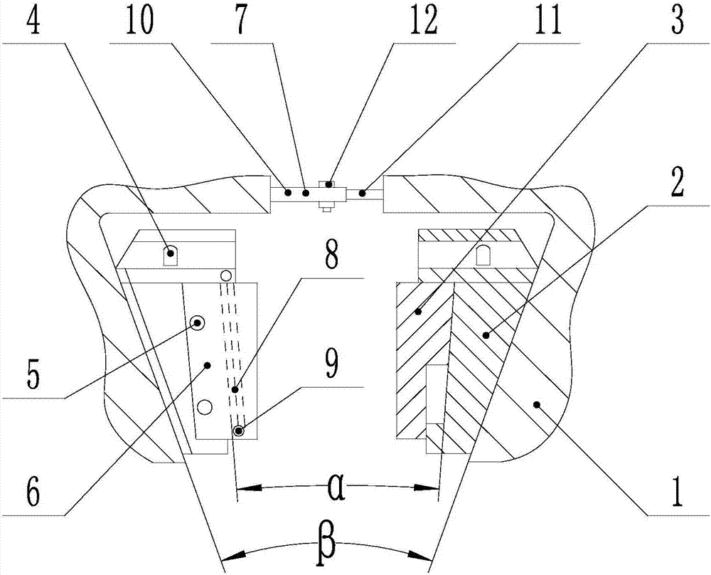
[0028] Such as figure 1 As shown, the clamping method suitable for the tensile strength test of cylindrical parts includes the following steps:

[0029] Step A: Set a wedge-shaped opening on the clip body 1, and install a wedge-shaped splint 2 in the wedge-shaped opening. The clip body 1 includes two parts, and the two parts are connected by a telescopic structure 7. The wedge-shaped splint 2 is set on the side away from the clip body 1. There is an inner concave part, and a wedge-shaped bayonet 3 is installed in the inner concave part of the wedge-shaped splint 2. The wedge-shaped angle α of the wedge-shaped bayonet 3 is smaller than the wedge-shaped angle β of the wedge-shaped splint 2. The wedge-shaped bayonet 3 is provided with an outer convex part, and its outer convex part is embedded and engaged with the inner concave part of the wedge splint 2, and the size of the convex part of the wedge-shaped bayonet 3 is smaller than the size of the inner concave part of the wedge-...


PUM


Abstract

The invention discloses a clamping method applicable to a tensile strength test of a cylindrical part. The method comprises the following steps: A, mounting a wedge-shaped clamping plate in a wedge-shaped opening of a clamping body, connecting two parts of the clamping body through a telescopic structure, inserting a wedge-shaped bayonet and a wedge-shaped clamping plate, mounting an ejector rod above the wedge-shaped clamping plate, and mounting a stop baffle and a tension spring outside the wedge-shaped bayonet and the wedge-shaped clamping plate; B, adjusting the length of the telescopic structure, fixing the telescopic structure, upwards starting the ejector rod, and putting a test piece into the wedge-shaped bayonet; C, pressing the wedge-shaped clamping plate by using the ejector rod, folding the wedge-shaped clamping plate, and driving the wedge-shaped bayonet to clamp the test piece; D, repeating the step C, and clamping the other end of the test piece; E, enabling the wedge-shaped clamping plate to open along two sides of a wedge-shaped included angle beta by the ejector rod, and loosening the test piece by the wedge-shaped bayonet. The wedge-shaped clamping plate has great expansion, the wedge-shaped bayonet has a small lock corner and is convenient to detach and high in self-locking property, and the method is applicable to cylindrical parts of different sizes.

Description

technical field [0001] The invention relates to a clamping mechanism, in particular to a clamping method suitable for the tensile strength test of column parts. Background technique [0002] Universal testing machine, a material testing machine integrating tensile, bending, compression, shearing, ring stiffness and other functions, is mainly used for mechanical performance tests of metal and non-metal materials. Ideal testing equipment for departments such as quality supervision stations. Universal testing machine is also called universal material testing machine, or tensile machine, double screw series, integrated structure of control, measurement and operation, integrating contemporary advanced technology, with high precision, wide speed range, compact structure, convenient operation, Stable performance and other advantages. It is suitable for tensile, compression, bending and creep tests of material samples and products such as plastics, waterproof materials, textiles, ...

Claims


Application Information

Patent Timeline
Patent Type & Authority Applications(China)
IPC IPC(8): G01N3/04
CPCG01N3/04
Inventor 刘宁周姝魏能强王伟
Owner API ZC PRECISION INSTUMENT CO LTD
Why Eureka
Try Eureka